


")

Here is the circuit diagram of lantern dimmer / flasher designed by Tony Van Roon:
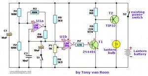
There are two circuit modes: dimming and flashing. The flasher mode is useful for warning other drivers of your troubles and it may be adjusted to have a very short flash duration for long-term use as when the car must be left on the shoulder over night.
Electronic Parts List:
R2 = 100K
R3 = 100K
R4 = 100K
R5 = 3K9
R6 = 3K9
R7 = 470
R8 = 100
R9 = 220, 1/2 watt P1 = 5K
C1,C3 = 10uF/16V
C2 = 0.01uF, ceramic
T1 = 2N4401
T2 = TIP32
U1 = LM358
L1 = Lantern Bulb
S1 = On-Off Switch
Lantern Dimmer Circuit Notes:
- S1 switch is used to activate the ‘Flashing’ mode.
- P1 is the dimmer potentiometer, you can adjust the dimming setting from here.
- Transistor 2N4401 can be substituted with a NTE123AP, the BC547.
- Transistor TIP32 can be substituted with a NTE197. Other transistor types might be work.
- The DC power supply or battery for this lantern dimmer / flasher is 6-12V.
There is nothing particularly critical about the resistor and capacitor values and the experimenter may change them, if desired. For example, a 10K-pot may be substituted for the 5K by increasing the 3.9K resistors by 2 also (8.2K would be fine). The 100K’s in the flash circuit may be a different value if the capacitors are also scaled (inversely–if the resistors are doubled, the 0.1 and 10uF are halved).
Good luck…