


")

We offer our readers the device is intended for anesthesia during dental treatment and prosthetics. Everyone knows what an unpleasant omissions occur during the processing of a tooth drill. It is understandable why the interest specialists to the problem of anesthesia during dental treatment. At the time it was suggested many ways, but none of them has been quite effective. The most promising was the so-called sound method of anaesthesia. He concludes that during the treatment the patient listens to the music program and white noise (a mixture of all the components of the audio spectrum of frequencies), fed to the headphones. Music has beneficial effects on the nervous system of the patient, and white noise dampens the focus of excitation in the cerebral cortex, cause pain.
The device for pain relief (sound analysator) was designed by the Leningrad engineer P. Weinbaum in collaboration with the doctor of the Military medical Academy. S. M. Kirov G. Mironenko. In the creation of the device provided invaluable assistance with technology V. Kuznetsov and F. Gulyantsi.
During the two years of operation in the dental clinic of the Military medical Academy sound analgizator always received good feedback from the patients. The device was exhibited at the 17th Leningrad exhibition of creativity of radio fans designers DOSAAF and was awarded the diploma of I degree.
Block diagram of sound analizatora shown in Fig. 1. The device consists of a bass boost, mixer unit (terminal patient), power supply unit and the tape drive mechanism with an endless loop of magnetic tape. Its purpose is to simultaneously play music program, and the white noise recorded on four tracks of the tape. The device uses low-impedance two-channel playback heads a working gap of 3 microns, tape type 6, the belt speed of 9.53 cm/sec.
Correction of the frequency response in the bass preamp stage allows to achieve high fidelity in the frequency range up to 10 kHz.
In Fig. 2 shows a schematic diagram of the audio analyzer. All four signals are removed by the magnetic heads with the tracks of the tape, the signal voltage is supplied to the corresponding pre-amplifier LF, transistors T1-T3 with Two pre-amp amplify the signals LF channel music (Am and BM), and two signals of the channel noise (Al and SS). At the entrance terminal of the amplifier WOOFER with passive mixers (R10, R11, R23 and R24) music and noise are mixed in the required proportions. After mixing and amplification of the signal voltage of the two terminals of the amplifiers woofers (T4-T9) from the Al+Am serving on one of the headphones, and DM+BM on the other, resulting in unnaturally effect. If necessary, the patient can adjust separately the magnitude of the level of music and noise from zero to maximum.
(click to enlarge)
A three-stage pre-amplifier LF transistors T1-T3 (PB). The amplifier covers a frequency dependent negative feedback depth 19 dB. The first amplifier stage is executed according to the common-emitter circuit. The playback head is connected to the input of the amplifier through a capacitor C1. The transistor used in the first stage must have a minimal level of noise. For approval of the first stage is applied with the following emitter follower, electrically associated with the first cascade. The third stage similar to the first. Negative feedback voltage is supplied from the collector circuit of the last transistor (T3) in the emitter circuit of the first through the elements C4R4R6. The output stage is loaded on the controller level, which is in a separate block - mixer.
The mixer unit, decorated in the form of a separate panel, is a resistive divider consisting of two coupled potentiometers R10 and R24) and decoupling resistors R11R23. Potentiometers act as regulators of the level of music and noise. Isolation resistors are needed to eliminate the mutual influence of the pre-amplifiers bass. The resistance of these resistors are chosen experimentally.
Final amplifier increases the signal level needed for normal playback in headphones. This amplifier should have low total harmonic distortion, high input resistance, low coefficient of amplification of the voltage and the additional correction of the frequency characteristics in the low frequency region (about 4 dB per octave).
Final amplifier is assembled on a six transistor (T4-T9), five of which are of the type p-n-p, and sixth (T9) - type n-p-n (a10).
The first and third stages, transistors T4 and T6 for the common-emitter circuit, amplify the voltage signal. The second and fourth stages transistors T5 and T7, (emitter follower) serve for matching the output impedance of the previous stages with the input impedance of the next.
The output stage is a push-pull power amplifier assembled on the common-collector transistors of different conductivity. This eliminates the need for a phase of the cascade. Amplifier covered deep feedback (26 dB), which drastically reduces the harmonic distortion. The feedback voltage depends on the frequency (frequency dependent feedback), so that achieving the additional correction of the frequency characteristics of the playback channel in the lower frequencies. Furthermore, the input impedance of the amplifier terminal served by the feedback increases. The amplifier is not critical to the load.
The power supply device includes a voltage regulator transistors TT. The reference voltage is removed from silicon Zener type D. The rectifier is assembled in a bridge circuit with four germanium diodes DA. The entire device is powered by AC power through a power transformer.
Kinematic diagram of the tape drive mechanism shown in Fig. 3. The use of an endless loop of magnetic tape, placed in a special cassette, simplified tape drive mechanism and use a low power engine type EDG-1M.
Fig. 3. Kinematic diagram of the tape drive mechanism: 1. Shaped disk 2. Roll film 3. The sleeve of the disk 4. Base, 5. Pinch roller, 6. Guide column 7. Drive shaft 8. Magnetic reproducing stereography, 9. Clamping bar, 10. Felt pad, 11. Loop magnetic tape. 12. The flywheel 13. Mylar strap, 14. The axis of the motor 15. The thrust bearing of the flywheel 16. The motor.
The tape device is a plastic box with a roll of tape length 230 m, which is wound on a disk based, freely rotating on the axis of the tape. Working diameter of the drive shaft 5 mm. Through the use of an endless loop tape rewinding is not necessary and the device is always ready for action. The tape drive mechanism is actuated by toggle switch power the engine and holds the drive roller to the shaft. Two stereo head positioned directly beneath the cartridge housing.
For proper contact with the tape heads used felt a special clamp, which is given at the moment of switching on of the apparatus.
Structurally, the entire apparatus is made as a separate unit (Fig. 4). The device's weight is 5 kg., Its size HH mm. the Top cover is removable.
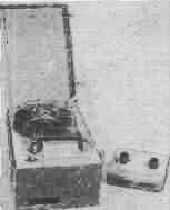
Fig.4
On the top panel of the apparatus fortified cassette with a device for mounting and clamping the tape to the shaft, two stereo head and the toggle switch on and off (Fig. 5). Stereo head closed with safety cover.
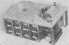
Fig.5
Under the panel Board is made of alloy In-95 with a thickness of 6 mm. it reinforced tape drive mechanism, comprising a motor-type EDG-1M, the flywheel shaft, the traction control and clamp (Fig. 6). On the same Board fortified whole electronic part, consisting of four-channel playback amplifier, power supply, power transformer and connecting pads.
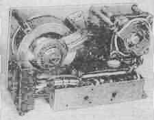
Fig.6
Preamplifiers playback is made as a separate unit. It is mounted on a box-shaped steel chassis. The dimensions of the chassis 160h80h40 mm. All four amplifiers are assembled on printed circuit boards and are separated from each other by screens (Fig. 5).
End amplifiers are assembled on two printed circuit boards are located on the other side of the mounting preamplifiers. The control panel is manufactured as a separate unit. The structure of this unit consists of two double potentiometer, playing the role of regulators and output pads for connecting headphones doctor and patient.
Authors: P. Weinbaum, G. Mironenko; Publication: N. Bolshakov, rf.atnn.ru