


")

Early in the last century L. A. cizewski proposed device, increasing the levels in the air of negative ions, positively, according to conducted studies, acting on the human body. It was called "chandelier Chizhevsky". In the future, such devices have been developed a lot, unite under the common name of the Ho The greatest difficulty with them the manufacturer is required to obtain efficient operation voltage of several tens of kilovolts, the author proposed articles used in high voltage block your phone "Mountain air" details of the node lowercase scan TVs the third to fifth generations: transistor KT838A with heat sink, transformer FA-PC, the voltage multiplier ON/27-1,3 and the thermistor ST15-2-220.
In articles published in the 80-ies of the last century, it was recommended to do frame "Chizhevsky" in the form of a spherical segment with a diameter of 1 m. to accommodate 400 needles and feeding voltage of 50 kV. In those years I managed to produce a source voltage of 40 kV and "chandelier" with a diameter of 0.8 m 250 needles, the room area of 16 mg saturation of the air with negative ions achieved 20…25 min, and after 15 min was a glut and the sharp points of the needles glow appeared. After several experiments I came to the conclusion that the optimal space for such "chandelier" with a diameter of no more than 0.5 m, containing 150 needles. At a voltage of 25…27 kV work like this "chandeliers" not accompanied by the glow and smell. Bringing her hand at a distance of about 20 see, you can feel the breeze. The air felt fresh, as in a mountain forest.
The scheme is made by me unit-AC Converter network voltage DC negative 25…27 kV depicted in Fig. 1.
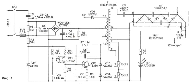
Although the unit is connected to the network via the transformerless circuit, due to the presence of resistor R10 much resistance when high voltage output circuit for the earth, caused by, for example, by touching the "chandelier", the current through the body touched will not exceed several microamperes, which is absolutely secure. A small voltage drop across this resistor is in operation efficiency "chandelier" does not reduce. Since the current consumed by the unit from the mains, and with him and his reactive power is limited by the resistance connected in parallel capacitors C1…C3, the operation of the generator high voltage circuit when its output is stopped. However, some the danger will represent the energy stored in the capacitors of the voltage multiplier, self-capacitance "chandeliers" and running wires to it. But at a voltage of not more than 27 kV this energy is relatively small, electrode will, of course, tangible, but not dangerous.
The pulse generator high voltage built at the transistor VT2 and the transformer T1 on the circuit with inductive feedback. Winding feedback (pins 1', 2') - further, it is wound on insulated wire free of other windings of the area of the ferrite magnetic core of the transformer. The number of turns in it are chosen experimentally. If they are less than ten, the efficiency of the generator after removing the circuit output is not automatically restored. It is necessary to disconnect the appliance from the mains by about a minute (to complete discharge of the capacitor C6 through the resistor R6) and re-enable. At ten revolutions to turn the power off is not required, using 1…3 after eliminating circuit, the oscillator begins to work, and if 15 not coils occurs and the generation breakdown, only slightly decreases the output voltage. the pulses supplied to the base of transistor VT2 from auxiliary generator on unijunction transistor VT1, facilitate run main generator.
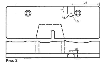
As you know, on a CRT TV with a multiplier receives positive voltage, and for generating ions necessary a negative. To get it, the voltage multiplier, the SE/27-1,3 are to be completed. First of all, you need to remove the "~" and "F", to bury their remains in the body of the multiplier is less than 1 mm and pour the sealant. Conclusions indicated by the letter V and the symbol of the corps, and join together soldered to the wire going to the resistor R10 and the "chandelier". The most difficult operation - fabricate missing in the output of the multiplier "A" (in Fig. 1 it is shown the thickened line). To get to the desired point, it is necessary, as shown in Fig. 2, carefully drill into the bottom surface of the housing of the multiplier hole a depth of approximately 6 mm, and then use a round file to enlarge it towards the rear surface. Solder to exposed the terminals of the capacitor and diode in the wire going to the capacitor C9, the hole also pour hermetical, such as paraffin.
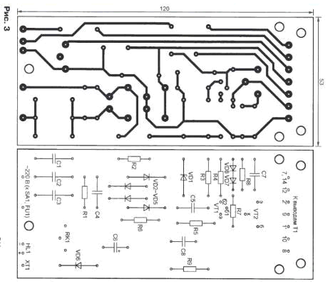
The printed circuit Board, which contains most of the detail of the device shown in Fig. 3.
Instead of diodes CDD in bridge the rectifier can be applied KD105B, and instead of the damping diodes of the same type (VD7, VD8) -CBM. Transistor KT838A can be replaced transistor KTA, but will have to make another heat sink. Capacitors (except oxide) film. K73-17V.
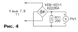
In normal operation generator the amplitude of the pulse voltage between pins 14 and 15 of the transformer T1 is about 9 kV, and the DC voltage at the output of the multiplier U1 - 25…27 kV. When no kilovoltmeter the operation of the generator can be checked by measuring normal voltmeter DC voltage at control point. 1 IN the nominal mode it should be about 220 V. Another way to connect to the terminals 7 and 8 of the transformer according to the scheme shown in Fig. 4, voltmeter PV1 - any multimeter is in the measurement mode of the DC voltage. It should show …6,5 6,3 V.
Author: Alekseev A.