


")

Microinterferometer provides a measurement of dose rate of gamma radiation on open areas, in industrial facilities, x-ray rooms and laboratories of up to 500 μr/s.
Schematic diagram of the device represented in Fig. 1. When exposed gamma radiation in the ionization chamber IK ionizes the air and attached to her the electrodes, the voltage causing the orderly movement of ions, resulting in through the camera there is a current of 10-12 orders of magnitude…10-9 A. This current flows through the R1 resistor and creates a voltage drop proportional to the power radiation. Voltage is applied to the grid of electrometer triode L1, working in the cathode follower. The last load is the divisor voltage R3-R6.
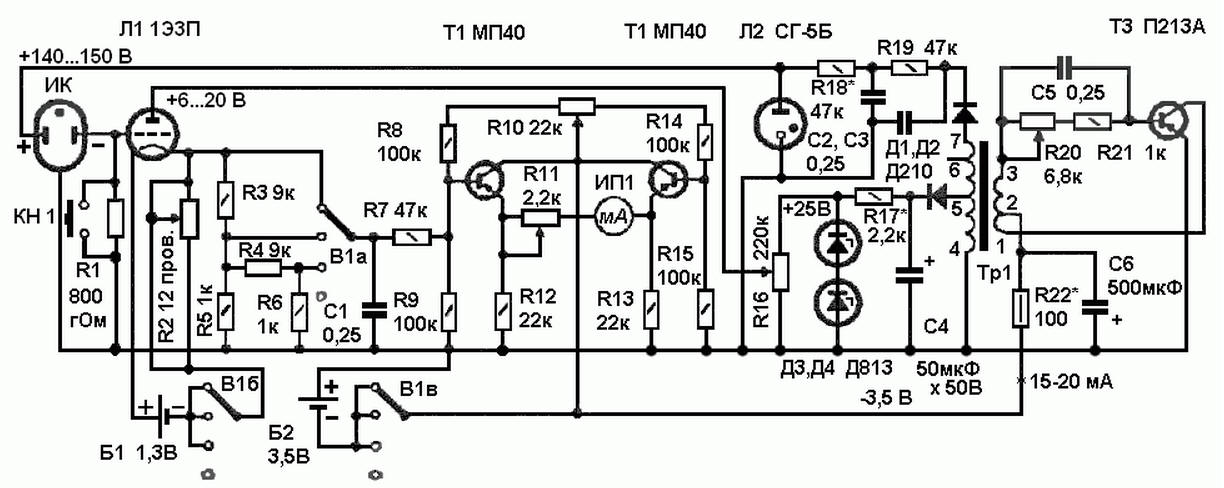
Fig. 1 (click to enlarge)
Depending on the expected dose rate switch B1 set limit measure 5, 50 or 500 Mr/S.
Transistors T1 and T2 is assembled with a DC voltmeter on balanced scheme with the microammeter IP at full-scale deflection current of 50 μa. The resistor R11 serves to calibration of the instrument scale.
The drive voltage for the transistor T3 provides anode voltage 6-20 In on electrometer triode stress and 140-150 In the ionization chamber. The latter is stabilized gas-filled Zener diode L2, anode voltage lamp L1 silicon Zener diodes D3 and D4. The required magnitude of this the voltage set by potentiometer R16. Mode the blocking oscillator voltage Converter set variables resistor R20.
The filament of the triode T1 is powered by element 373 or one item from the battery flashlight 3336L. The filament voltage of the lamp set in the range of 0,5-0,7 In using variable wire wound resistor R2. Converter voltage and transistor voltmeter supplied from the battery B2 (3336L). Installation meter voltmeter by zero is carried out by adjustment of the variable resistor R10, button KN at the bottom of the resistor R1.
Microinterferometer mounted in body size HH Ionization mm. the camera is built into the same housing.
The Tp1 transformer of the blocking oscillator formed on the yoke Sh. Data windings: 1-2 - 300 turns of PEV-2 0,1; 2-3 - 500 turns of PEV-2 0,08; 4-5 - 800 turns of PEV-2 0,1: 5-6 - 3200 turns of PEV-2 0,05; 6-7 - 1000 turns of PEV-2 to 0.05.
Author: S. Vorobev