


")

Aeroionizator "Chizhevsky Chandelier" for many decades proved your ability to "improve" the air of our homes, filling them with life-giving negative air ions. About this device the magazine "Radio" repeatedly told in its pages.
Based on the ideas of the scientist, many designers with varying degrees of success trying to develop a small ironizator which do not replace "Chandelier Chizhevsky, but can create indoor atmosphere in which to work easier.
We offer our readers one of these designs, which was created candidate of technical Sciences Viktor Korovin (Russian Federation patent No. 2135227). It tested in the burn centre of Institute. Sklifosovsky and received a positive opinion, has a health certificate.
Development hoboго of aeroionizatora was undertaken with the aim to create a compact home device. But before there was a completed design, the author conducted a lot of experiments. At first they were carried out with a simple trinistorny high-voltage Converter, which later had to be abandoned on reason-made electromagnetic interference and small efficiency. Was later made anotherstory Converter, which underlies described aeroionizatora.
Both types of converters allowed to get on ionizing electrode the negative potential of 80 kV. To change the voltage on the electrode used adjustable autotransformer, the output of which supply voltage frequency of 50 Hz was applied to the transducer.
The voltage on the electrode was measured by a voltmeter with the magneto switches indicator (current full deflection 50 μa) and an additional resistor the resistance of 2 Gω. composed of 20 series-connected resistors 100 MW each). Thus, the limit of the measured voltage was 100 kV.
In the experiments, the electrode in the form of a thin beam pointed at the ends conductors (in the form of "dandelion"). The measurement results showed that already at the potential of 20 kV at a distance of 2 m from the ionizing electrode concentration ions is at the level of the maximum permissible sanitary norms. Hence any large values of the potential on the electrode is minimal the distance at which an enduring human presence, becomes even more.
Another important conclusion is that the concentration of light ions significantly decreases when the electrode is about 10 times on each meter removal. This decline is due to recombination (loss) ions and their the capture of aerosol particles polluting the air. Because recombination the average time of sushestvovanija (lifetime) light ions is very limited and practically does not exceed ten seconds. So it is essentially impossible to create in the room a uniform distribution ions, and especially to try to saturate the air in several rooms, if the ionizer is installed only in one of them.
It is useless to try to stock up on air ions for the future. After the unit is switched off their concentration quickly falls to the background level. But the good job the device will still manifest itself for a long time in the form of clean air. If necessary, the saturation of air ions of several areas of need each of them be equipped with ionizer or use a portable device.
With that said and was developed by compact aeroionizator, called the author of "Korsan" (Fig. 1).
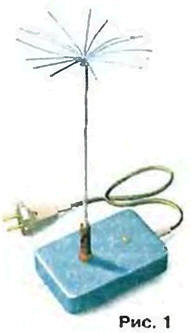
High-voltage transformer and the corona electrode in it constructively combined into one unit through the connector. As the Converter housing used half of a plastic soap dish external dimensions 110x80x30 in mm. hosting fee onetransistor oscillator with a transformerless mains supply of 220 V. the diode voltage multiplier, a current-limiting a protective resistor and a nest for fastening of the electrode.
On the device there is no power switch, because to use it impossible due to the occurrence of static charge on the human body when approximation to a working device. Therefore, aeroionizator equipped with a long (not less than 2 m) flexible power cord with a plug on the end, which is carried on switching on and off of the device.
The size of the body to accommodate for the diode multiplier at 40 kV and more. But based on the experience of three years of operation of the ionizer at home and in medical institutions, should be recognized as suitable for domestic use the choice of the potential on the electrode 15 to 30 kV.
The electrical circuit of aeroionizatora shown in Fig. 2.
AC voltage 220 V with diode bridge VD1 and the capacitor C1 is converted into DC voltage of about 310 In supplying high-voltage oscillator. It is made on the VT1 transistor and the transformer T1. Winding I and the capacitor C2 form a resonant circuit included in the collector circuit transistor in series with the resistor R2 and indicating LEDs HL1, shunted by the resistor R3. With the winding II through the coupling capacitor C3 to the base of transistor voltage is positive feedback. Resistors R4-R6 determine the mode of avtomashine at the base.
To increase the winding III develops an alternating voltage with an amplitude of about 3 kV, which is applied to the multiplier diodes VD2-VD11 and the capacitors C4-C13. At ten multiplier stages is achieved by the negative potential of 30 kV. When use vesemichastnogo multiplier at the output will be 24 respectively kV. The output of the multiplier is connected to the socket x2 through a protective resistor R7, limit the current in case of accidental touch corona electrode to a safe values.
The most crucial part of a device - high voltage transformer (Fig. 3). He performed on odinnadtsatistrunny cylindrical frame 2 with the magnetic core 1 8 mm ferrite MN. Increasing winding III contains 3300 turns wire PELSHO 0.06 and evenly laid in sections of the frame 300 of turns in each. The winding of I contains 300 turns of PSLO 0.1 and reeled in three OC Yes on sleeve 4 located on the edge of the frame from the left on the output circuit of the winding III. Four turns of the feedback winding II is wound wire PELSHO over 0.1 windings I and separated from it by a layer of insulating tape (Scotch) 3.
The length of the frame with the magnetic core can be in the range 70… 100 mm and is determined by the size of the housing. Frame 2 and the sleeve 4 of the transformer can be glued from 3-4 layers of paper used for printers or copiers. Cheeks for separate sections can be made of heavy paper with a thickness of 0.3…0.5 mm. But ideally, of course, to carve sectional frame made of a dielectric material (Teflon, polystrap, plexiglass, hard rubber or dense wood).
The beginning and end of the winding III fluster to the terminals 5, glued to the edges of the frame. The conclusions are easy to execute from a single-conductor copper wire with a diameter of 0.4…0.5 mm. but you can't create short-circuited turns. These findings transformer attached to the Board. The terminals of the windings I and II was being served to the Board of compliance with specified in the scheme of phasing.
The design allows operation of the transformer without any special the impregnation.
Best results will be obtained if instead of the one in the diagram bipolar transistor KTA to apply any transistor of BIT series KB. CP or KPA (the output of the gate is used as a base, the drain - manifold, the source - the emitter). Diode bridge VD1 - favourite, designed for rectified current is not less than 100 mA reverse voltage is not lower than 400 V; rectifying columns VD2-VD11 - CCB-CCG or any of the series CC. CC - CC. Capacitor C1 is a capacitance from 1 to 10 µf a voltage lower than 315; C2. C3 - any type, but on C2 working voltage of at least 315; C4-C13 - K15-5 capacity 100-470 pF voltage of 6.3 kV. Led - any with visible radiation. The Resistors R1-R6 - S2-23 S2-33. MINTS. OMLT; R7 is C3-14-0.5 or C3-14-1.
When using non-defective parts and correct installation of aeroionizator begins to work immediately. Control of operation of the oscillator and the measurement of its major settings convenient to carry out with the help of the milliammeter AC measuring range 25-50 mA and oscilloscope, allowing to observe on the screen an electrical signal with a span of at least 600 V. the current Meter allows to identify and minimize consumption from the mains power, and oscilloscope visually monitor and optimize the operation of the device, as well as indirectly to determine the value of the DC voltage at the output of the multiplier.
Measuring AC include in any gap power cord. But before inserting the power plug X1 into a mains socket, remember that aeroionizator eats without isolation transformer and, consequently, any element of is under threat to human voltage relative to the neutral wire. So be aware of the safety precautions and observe them!
The first time it is advisable to do without the diode multiplier. In the absence of generation (control oscilloscope connected to the collector of transistor) need to pay attention to current consumption (quiescent). If it does not exceed 1 mA may, the transistor has a low current transfer ratio base, and its it is better to replace. But you can try to increase the quiescent current selection resistor R5 with less resistance
If the quiescent current is in the range of 2 to 5 mA. and the generation of no. the cause of her the absence may be incorrect phasing of the conclusions of the windings of the transformer. In this case is enough to swap the ends of any of the windings - I or II. If the generation does not occur or vibrations, but very small amplitude (the transistor operates without cut-off), it is necessary to increase the number turns (1 …2) the feedback winding II.
In a normally operating the generator (the frequency is 40…60 kHz) peak voltage on the collector relative to the common wire is in the range 500…600 volt, angle the cutoff of the transistor is close to 90° (the transistor is saturated during the quarter period), the current consumption does not exceed 15 mA. In this mode the transistor produces power less than 1 watt, and can be used without a heat sink.
It should be borne in mind that the efficiency of the generator is associated with the angle of cutoff of the transistor. The value of this parameter is easy to optimize using an oscilloscope selection resistor R4 and the voltage across the winding II. The more voltage (more turns) and smaller the resistor, the more the cutoff angle. The dependence of the efficiency on the angle the cutoff is of the extreme nature, and the optimal mode is achieved when the values of the angle of 80-100°.
After you have finished the adjustment of the generator can be measured with oscilloscope voltage amplitude increases the winding III. To do this easier just take advantage of the capacitive voltage divider (Fig. 4). The Capacitor C1 must be a working voltage of at least 3000, for example SWИ, and a capacitor C2 - any type. The coefficient of the fission chain at specified values of capacitors and the input capacitance of the oscilloscope 100 pF to 100.
With sufficient accuracy the voltage on the ionizing electrode (on the nest x2) determined by multiplying the peak value of the voltage boosting winding III the number of stages of the diode multiplier.
At the end of the settings it is possible to test the operation of the device connected with multiplier. For this it is necessary to connect a step-up winding wires III length less than 10 cm and place on a sheet from a good insulator (plexiglass, the plated hardened paper, etc.). The best way to check is to measure negative the potential at the output of the multiplier relative to a grounded wire with high-voltage voltmeter. But can be limited and simple switching. In normally the inverter is running, usually between the terminals of the capacitor diode multiplier corona discharge occurs, followed by a characteristic a hiss and the smell of ozone, but it is possible and spark discharges.
To operate aeroionizator like that, of course, impossible. Required the minimum sealing of the multiplier dielectric compound. If the decision on the sealing of only one multiplier, the design of the ionizer must be such that the distance between the corona electrode and the high voltage unit is not less than 1 m. otherwise, the reliability aeroionizatora drops dramatically and it can fail after a few months. In the case of the high voltage unit available through the joints and gaps begin to leak microcurrents, with time passing in spark discharges that not only due to the inevitable settling of aerosol particles on it the surface and their penetration into the body.
In the described construction sealed all parts of the device with epoxy glue The EAF. Before pouring the nodes and elements are mounted in a dielectric housing with wall thickness not less than 1.5 mm. it is Necessary to take measures to eliminate possible leakage of resin through the holes used for mounting the connector, LEDs and input power cord. For this purpose, the diameter of the holes should be accurately aligned with corresponding elements. You can use advanced sealing these places PVA glue, "Moment", BF, etc.
Glue the EAF is used in accordance with the attached manual. Before mixing with the hardener to the base heated to a temperature of 70…90°C for increase the fluidity and speed up the curing process. But it is necessary note that after mixing of the components of the hardening reaction occurs with a lot of heat. When the amount of resin is more than 50 ml can to happen with the self-boiling and curing within a few minutes. It is therefore necessary to use a filler (silica or river sand), entered in already prepared to the fill mass in a volume ratio of 1:1.
Operation of the device is possible not earlier than 24 hours after pouring of the housing.
Author: V. Korovin, Moscow