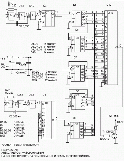
This design was created after analyzing the circuit Vlad Pomelova http://radioam.nm.ru/schemes.html and some study the brand of the device:

This is the usual generator, an outstanding range of frequencies from 60 Hz to 12.5 kHz, collected on normal TTL chips. This design could assemble and analog elements, and on PIC controllers, but I just used the parts that lay in my Desk for a long time without any movement.
The signal frequency of 50 kHz with generator D1 is a divisor D3 and with him meander 25kHz comes to счетчикиD5, D6 and the 16 kHz square wave on D7, D8. From the outputs of counters signals are the inputs of the multiplexer D10. The multiplexer switches the channels according to the signals from the counter D9. The signal frequency of 12 Hz from the generator goes to D2 D4 .
Here we have used IE as a divide-by-64 since it is difficult to obtain sustainable generation of 0.2 Hz. As the first emitter I used SN-3 but then set phone earpiece TK-67, and the radiation power has greatly increased despite the loss of the radiation energy in the upper frequencies. With the primer I took off the top cover and membrane secured with tape at the edges.
The device is used in our family and really helps against boils, colds, back pain, etc.
Chip O
Frequency, Hz
D5-3
12500
2
6000
6
3000
7
1500
D6-3
800
2
400
6
200
7
100
D7-12
8000
9
4000
8
2000
11
1000
D8-12
500
9
250
8
120
11
60
Author: Alexander Zhavoronkov, This email address is being protected from spambots. You must have JavaScript enabled to view it. ; Publication: www.vitafon.ru, www.cxem.net


