


")

In the February issue of the journal editors appealed to readers with a request to send your circuit design power supply "Chizhevsky". To this request, one of the first responders is the author of published article, proposed several variants of such blocks. Among them - the power supply with the use of industrial television voltage multiplier. By the way, the same version is used in their construction A. Michael from St Petersburg - he said this edition.
It is known that the DC voltage of negative polarity on the "chandelier" must be at least 25 kV, almost as at home on "chandelier" is desirable to bring the voltage of about 30 kV. Based on these figures were developed by the proposed power supply.
Diagram of the first embodiment of the power supply unit shown in Fig. 1. Mains voltage coming through the plug HR and the switch SA1, is supplied to a bridge rectifier made on the diodes VD1-VD4. Rectified voltage is filtered by capacitor C1. In the end, on this capacitor there is a residual voltage of about 300 V, which is used to power relaxation oscillator composed of elements R3, C2, VS1, VS2.
The load of the generator - winding I of the transformer T1. With its winding II pulses the amplitude of 5 kV and a repetition rate of 800 Hz is fed to the multiplier voltage, assembled diodes VD5-VD10 and capacitors NW-C8. The resulting the output of the multiplier constant voltage of about 30 kV is fed through current-limiting resistor R4 to the "chandelier".
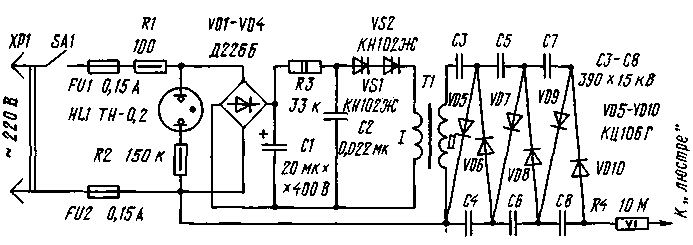
Fig.1
Table 1
Transformer
The number turns
Wire
Resistance In Ohms
FA-A, FA-B
720
PELSHO 0,1
152
TBC-110JBC-110M
940
PALDAO.1
240
FA-110A
1000
Sew-2 0,1
250
FA-L
1300
Sew-2 0,09
430
FA-L
900
Sew-2 0,08
310
FA-LS
940
PELSHO 0,1
240
FA-LA
1200
Sew-2 0,1
380
FA-AM
900
Sew-2 0,08
280
FA-L
1290
PAM-2 0,1
410
Neon lamp HL1 - on indicator power supply. Resistor R1 limits inrush current, inevitable when charging the capacitor C1. Fuses FU1 and FU2 triggered by the failure of elements of the rectifier or high voltage of the voltage multiplier.
The transformer T1 is converted flyback transformer from black and white TV. Its high-voltage winding II leave, the rest are removed and instead of them winding is wound I - 24 turns of wire sew diameter 0,5…0,8 mm To fit almost any flyback transformer, because the data of their secondary windings differ slightly (for some of them, they are given in table. 1). Moreover, the output voltage of the unit if necessary, can be increased by adding another cascade multiplication. Lower circuit output winding II is its beginning, the conclusion is closer to the magnetic circuit.
Diacs VS1, VS2 - series KN or outdated D. According to the data given in table. 2, include a series so much diacs, how many can provide the total switching voltage of about 200 V. the Capacitors NW-C8 - JI, COB or other capacity of at least 100 pF rated voltage not lower than 10 kV; C1, C2 - for a voltage not lower than 400 V. Is indicated in the diagram, the diodes VD1-VD4 can be DB, DW, KD105B, QDV.
When mounting the high-voltage unit, it is desirable to provide a chaser multiplier compound with high resistivity, for example, paraffin. In this respect, a promising option is the use of ready-made multiplier
Table 2
Type dynistor
Switching voltage,
CNA.DA
20
CNB.DB
28
CNV.DV
40
KING,DG
56
KIND.DD
80
KN E
75
CNG.DJ
120
KNEE.DI
150
UNIVERSITY of 8.5/25-1,2, used in color TV sets. However, in the TV it is designed to receive the positive voltage supplied to the anode of a CRT, we also need negative voltage for the power "chandeliers".
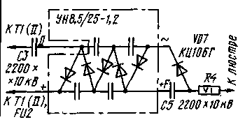
Fig.2
To reverse the multiplier, enough to make another conclusion - D (Fig. 2) neat drilling and sawing compound to provide access to the desired point internal mounting of the multiplier. For this multiplier have so that before you were unturned type designation and conclusions (the slot for fixing the multiplier on the Board will be on the right), then the location of the elements in the compound will correspond to their location on the schematic diagram. The two horizontal ledge around the edges of the multiplier are the locations of the capacitors, and we are interested in the point D is at the left edge of the upper ledge.
If you were to use a modified multiplier, the output voltage will not exceed 25 kV. Therefore, the multiplier will have to add another cascade diode VD7 and the capacitor C5.
The values of capacitors C3 and C4 (types K15-U1, K15-4, K15-13, K73-13) correspond to those that are in the multiplier.
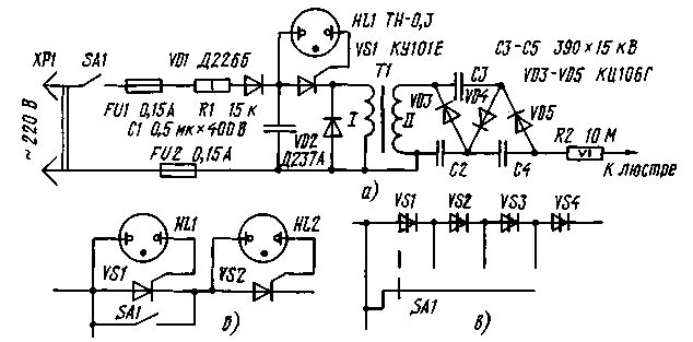
Fig.3
Diagram of another version of the power supply unit shown in Fig. 3. The relaxation oscillator in it is made on the elements R1, VD1, C1, HL1, VS1. He works with the positive half-cycles of the mains voltage, when the capacitor C1 is charged up to voltage enable analog on dynistor neon lamp HL1 and SCR VS1. Diode VD2 dampens the pulses of the self-inductance of the primary winding of the boosting transformer T1 and allows to increase the output voltage of the power supply. When shown in the diagram the three stages of the multiplication of the output voltage is 26 kV. Neon lamp is not only an element of analog diacs, but also the indicator of inclusion of a unit in the network.
High voltage transformer - homemade, it is wound on a segment of the rod with diameter of 8 mm and a length of 60 mm ferrite MN. First primary winding is wound 30 turns of wire PELSHO of 0.38, and then secondary - 5500 turns PELSHO 0.05 or larger diameter. Between the windings and every 800…1000 turns secondary winding lay a layer of insulation from ordinary PVC insulation tape.
In any of the blocks it is possible to introduce discrete (and, if desired, and smooth) multi-stage adjustable output voltage switching is included in series circuit analogues of diacs (Fig. 3,6) or diacs (Fig. 3,in). In the first embodiment are provided with two stages of regulation, the second one to ten (when using diacs CNA voltage enable 20V).
As a high-voltage wire connecting the power unit with "chandelier", the author used the TV antenna cable RK with a diameter of 8 mm with removed outer insulation and the braided shield. In
Author: V. duck, Schelkovo, Moscow region; Publication: N. Bolshakov, rf.atnn.ru