In the "Ham" was published by the apparatus for magnetoterapia - therapeutic heating of the body in a magnetic field of high frequency [1]. Offer a more powerful machine, suitable for the treatment of internal organs. I recall that in the magnetic RF field heats only the bloodstream as magnetodielectric lossy (in the person of 5 liters of blood have 1 kg of iron). In this case the body, as a large self-regulating system, strengthens and enhances the bloodstream for as long as necessary to stabilize the temperature of the body. But increased blood circulation (microcirculation) has a strong therapeutic effect. Magnetoterapia successfully treats the majority of inflammation (eg, the common cold). And in combination with medications and method of thermochemotherapy, she is truly universal.
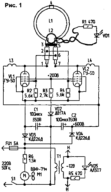
The new device is a two-tube push-pull oscillator with up to 150 watts at a frequency of 40 MHz. Diagram of the apparatus shown in Fig.1. Generator combined with the framework emitter which simultaneously serves as an oscillatory circuit of the generator.

Due to power in the center of the frame, the magnetic field strength in the tens of amperes per meter. Capacitor resonant circuit has the internal capacity of the segment of the cable, forming a frame. When turned on, this shows the capacitance applied to the ends of the inductance. Positive feedback is fed to the control grid of lamps through capacitors, which serve small isolated segments of the braid at the ends of the cut cable. These segments braid reduce the inductance of the findings of the frame, increasing their effective diameter. Powered generator from the rectifier 220 V network voltage doubler. To the anodes served 600, the screen grid is about 200 In considering the damping of the voltage on the Zener diode and the ballast resistor.
The design elements of the scheme. High frequency inductors L3, L4 is 2 m wire MGTF-0,14 wound round on a segment of coaxial cable without braid (i.e. its internal insulation and lived) with a diameter of 9 mm or on a special frame. The ends of the conductor are fixed with rubber rings cut from a tube with a diameter of 4...5 mm. From one side of a piece of cable laid bare lived on 3...4 cm and wrapped in eyelet for attaching the choke to the chassis.
Communication loop L2 - oval shape, with an area of several square antimirov of well insulated wire (MGTF). Frame L1 is the segment of coaxial cable RK50-9-23. If not, it is possible to replace (as preference): RK50-4-21, RK50-2-21, RK50-7-11 or RK50-4-11. In any case, the cable it is advisable to take a heat-resistant and elastic, retains its shape when bending. If you use the cable with outer fiberglass insulation on top of worn rubber tube. The cut length of the cable is 1m. the Scheme of cutting shown in Fig.2.

Fig.2
The numbers:
-1,7 Central lived on the bare length of 5...8 mm, internal insulation - at a length of 10 mm;
- 2, 6 - untouched parts of the cable length of 45 mm;
- 3, 5 - breakage braid over a length of 10...12 mm internal insulation saved. The ends of the slit (with an awl and nail scissors) braid is folded on the surface of the cable towards the middle of the segment;
- 4 - the gap braid over a length of 15 mm cut exactly in the middle of the cable.
All ruptures braid wrapped PTFE tape to the level of external insulation. The top segment of rubber is worn or corrugated acrylic tubing (plumbing) with a diameter of 20 mm, the ends of which zaplavlyayutsya thermoplastic. Ruptures braid can also seal the segments of the outer plastic insulation of the cable by wrapping them with adhesive tape. Section of the cable is folded in a round frame, folded the ends of the braid are wound two or three turns of bare wire and propaedeuse, forming the jumper. The distance between the ends of the cable in this place - 5...8 mm.
The sequence of cutting: perform gap and insulation phase 4, then thread the cut ends of the cable through the holes in the cover plate and the front housing cover, then make the rest of the cutting.
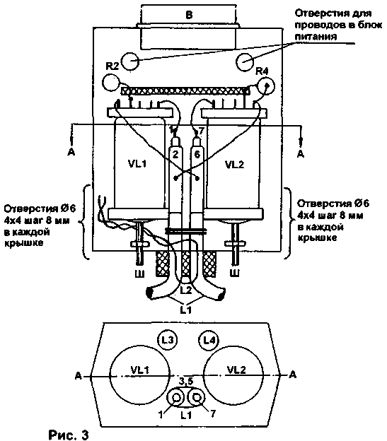
The device is mounted in two buildings the size of Hg mm of high-impact polystyrene. In one case the generator is placed in another power supply. Hull are glued blind sides (with glue "Moment"). Double wall forms a chassis on which are mounted all of the elements of the scheme - a method of pressing a hot soldering iron findings and fastening clamps from wire with a diameter of 1 mm into the plastic. The arrangement of elements in the generator unit shown in Fig.3.

Fig.3
To the contacts of the tube sockets are soldered first stretches of bare tinned wire with a diameter of 1 mm and a length 20 to 30 mm. the end of the wire is put in the "eye" sockets, bent and crimped, and these conductors are soldered conclusions of the circuit elements and wires. Cathode the findings of the lamps are connected by a bus from the wire, which is shown in the figure. The length of the anode connecting wires anymore, they dress up heat resistant insulation. For frame L2 in the plate and the lid, drill holes directly next to the cable frame L1. Outside the conductor L2, it is desirable to zaplatit thermoplastic. Fixation bulb is stud and nut that rests against the front cover. The distance from the cover to the lamp - 25 mm. For cooling the lamps used the blower power wires through a resistor (to reduce hum). You can apply the fan to 12V, powering it from the filament voltage of the lamp through a rectifier (diode, capacitor 20 mcfh In and the 10 Ohm resistor). The inner surface of the generator unit is glued over foil to reflect heat away from the plastic. Installation of power supply - arbitrary places in the body in excess. The transformer T1 is fixed to the unit mounting the unit to a tripod through the cover. Lamp socket you can do yourself. Nests are made of bare wires with a diameter of 1 mm. On the drill bit with a diameter of 2.2...2.3 mm from the circumferential cylindrical spiral height 8...9 mm, which is applied to a toroidal winding 10 to 12 turns of bare wire stalistoy diameter 0.3...0.35 mm (nichrome). The ends of the spiral are passed through apertures in the Board of fiberglass or Micarta thickness of 1.5...2 mm and are twisted from the other side of the Board. The holes for the ends of the slots are arranged radially in a circle (as are the bulb pins).
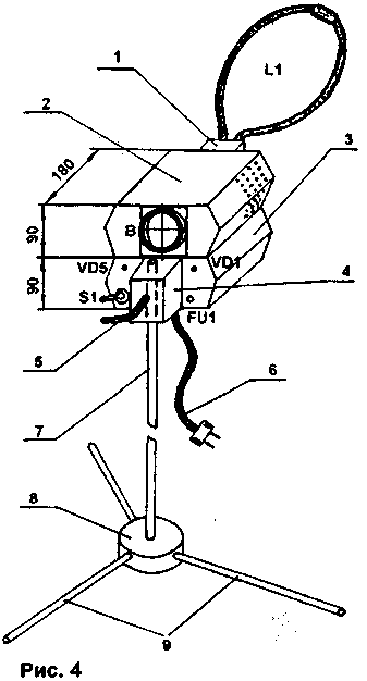
General view of the apparatus shown in Fig.4.

Fig.4
The numbers: 1 - trim, 2 - generator unit, 3 - power supply unit, 4 - unit mount to the tripod, 5 - screw with a handle, 6 - power cord 7 - stand tripod, 8 - node element fixing tripod, 9 - tripod legs.
Plate 1 (thickness of 20...30 mm), attachment 4 and 8 are made of caprolon, plexiglass or thick wood.
The elements of the tripod 7, 9 - fiberglass or aluminum tube (ski poles). You can use wooden handle from a garden tool.
Effective form field emitter-frame has the form of a somewhat flattened sphere, resting on a frame. To treat this "sphere" should be combined with the patient body. For example, in the treatment of arthritis frame wear on the limb or apply to the affected area on the side. For all inflammations in otolaryngology frame advantageously be curved in the plane in half at a 90° angle and the bent portion attached to the neck, and near to the body part to hold on the nose. This place bends closer to the ears, and at last felt the warmth. Thus treated, the inflammation of the nasopharynx is the space that is available only by invasive methods. To treat bronchitis, pneumonia, hepatitis, and other inflammations of the internal organs of the frame should be put flat on the body surface against the body. The indicator apparatus(field indicator), in addition to the LEDs, is an incandescent lamp (6.3 V) connected to a coil with a diameter of 3...4 cm (a neon light in a magnetic field does not illuminate). When heating the solid parts of the body (chest, abdomen) on the surface put the indicator field and bring the frame of the apparatus at such a distance, where the light bulb glows most brightly (usually 1 ...2 cm). To secure the frame using foam pads. When heated back (degenerative disc disease) the unit easy to turn up the power supply - then the case does not interfere with the procedure. Session duration is from 5 to 30 minutes (for the head - 10). Neuritis (sciatica) in the acute form are well treated by sessions for 5...7 minutes in half an hour. Chronic inflammation - sessions once a day or every other day. Usually enough 3...10 sessions. Ten-year experience of clinical use of magnetothermic not revealed any harmful side effects, treatment amenable all inflammation, which end in "-it". However, the correct diagnosis, which will establish the doctor.
The device emits very little in the surrounding area and fit well within the established background level.
The author suggests the question: why the generator is not on the transistors? The answer is the more expensive transistors (suitable worth tens of dollars). Furthermore, the bulb allows the case temperature 200°C, and the transistor 60°C, i.e., you need a good radiator. Win in volume still does not work. Finally, the gain of the lamp is 40 dB, and a transistor (good) - only 15 dB.
Literature
1. Ham, 1999, N6, P. 31.
Author: Yu Medinets, Kyiv; Publication: N. Bolshakov, rf.atnn.ru


