


")

In Fig. 1 shows a diagram of a simple low pass filter (LPF), frequency cutoff of 35.6 MHz. The filter is designed for input and output impedance 50 Ohm. The inductance of the coil L1 to 0.45 µh. It is frameless and has 8 turns of PEV-2 in diameter of 1.6 mm, wound on a mandrel of 10 mm diameter (winding ordinary round).
When removing the frequency response of the filter, collected under this scheme, revealed deviations from calculation. The losses in the filter at the maximum operating frequency (29,7 MHz) amounted to 3 dB, while the attenuation was supposed to be only at the cutoff frequency (curve To in Fig. 2). It may have occurred due to the finite quality factor of the circuits, or due to the inexact matching of the parameters of the real element calculation. That this is not an error of measurement of frequency response, says the dependence of VSWR against frequency. The growth of the CWS occurs at the same frequencies, and growth losses, i.e. these two curves clearly correlate.
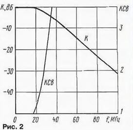
Loss in the transparency band can be reduced by choosing an inductor L1 or by selecting in the calculation of the elements of the cut-off frequency slightly higher. While AFC how would a shift to the right and slightly reduced attenuation in the band boom. With the increase of the cutoff frequency will improve and SWR in the frequency range 27 to 30 MHz.
In Fig. 3 shows a diagram of the notch filter m-type, the frequency of rejection which selected equal to 57.2 MHz. Near this frequency is the first frequency band a TV channel. Coil L1 is the same as in the P-filter, only she has 7 turns and the inductance of 0.35 µh.
To improve the efficiency of filtration these filters were combined (Fig. 4).
AFC the combined filter and the dependence of VSWR with frequency for input when connecting to the output load of 50 Ohms is shown in Fig. 5.
The inductance of the coil L1 to 0.45 µh, a L2 - 0,35 mH. Instead of the capacitors C2 and C3 can be set capacity 150 pF.
The filter is best performed in a metal case. The parts of the filter have divide the shielding wall. The distance between the walls of the filter and the inductors should be at least twice its diameter. As the filter design strongly influences its options, and to consider all parasitic factors impossible, every instance of the filter needs to establish. The frequency the cutoff (and hence the attenuation in the upper part of the strip transparency) can indirectly be determined using an SWR meter. To determine the frequency of rejection will need an RF the RF generator and voltmeter. At the time of establishing the filter is loaded up to the equivalent of the load impedance of 50 Ohms.
When removing the AFR should consider the dependence of the output voltage of the RF oscillator frequency due to the fact that the band rejection input impedance filter differs from 50 Ohms and is complex in nature.
Author: O. Dolgov, Moscow