In everyday life there is often a need to feed the appliances from the batteries through a DC / DC Converter in AC. Most of the devices, the voltage of the sinusoidal form, it works fine and generated from such converters rectangular pulses. Unfortunately, not one of them are asynchronous motors, for example, activating the circulation pump systems heating. A significant proportion of harmonic components, which are part and parcel non-sinusoidal voltage, in such engines becomes useless heat, rest - break the uniformity of the rotation of the magnetic field. To to suppress harmonics, the required filter circuit and method of calculation of which suggested by the author published article.
To power the induction motor from the voltage source rectangular shape best suited filter, the circuit of which is shown in Fig. 1. It transmits to the first harmonic load almost without attenuation, enough strongly attenuating higher.
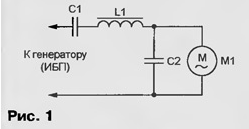
The equivalent circuit of the filter, loaded at the motor shown in Fig. 2. The engine presents a parallel the connection of active resistance Rd and self-inductance Lд. Posted also, R1 is the resistance of the coil (inductor) L1. Both oscillation circuit - serial L1C1 and parallel LДС2 is configured to the pulse repetition frequency of the input voltage.
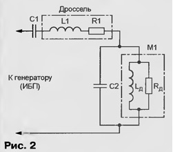
Calculate the filter elements designed for induction motor, the signboard which shows the following parameters: voltage U - 220 V, frequency F - 50 Hz, power R - 75 W, cos<φ - 0,6. For further calculations will be required also the value of the circular frequency Ω = 2πF = 6,28·50 = s-1 and the value sinφ =√1- cos2φ = 0,8.
The active constituent of absorbed motor current lR = P/U = = 75/220 = 0,341 And, jet - LL= IR(sinφ/соsφ)- 0,341· 0,8/0,6 = 0,454 And where Rd = U/IR = 220/0,341 = 645 Ω; Xl= U/IL = 220/0,454 = 484 Ohms; Lд = XL /φ = = 484/314 = 1,51 GN. To the resonant frequency of the circuit LдС2 was equal to 50 Hz required capacitor C2 = = 106/(φ2Lд) = 106/(3142·1,51) = 6,58 UF.
Assume that the L1 installed in the filter choke from the lamp with fluorescent light with power of 80 watts. On the nameplate of the inductor can be found the following data: supply voltage U - 220 V, frequency F is 50 Hz, rated operating current IH is 0.84 A, соsφ - 0,5 (sinφ =√1-cos2φ= 0,866)
At resonance circuit CS reactive component of the motor current compensated current of the capacitor C2. The active component of the motor current (0,341 (A) flowing through the inductor, is much less 0,84 And, therefore, temperature of the inductor is not of concern
The power consumed by the lamp from the mains, equal RSV UIн = 220 ·0,84 ·0,5 = 92,4 W, of which 80 come from its lamp, and the rest of 12.4 dissipates R1 - the active resistance of the inductor. The resistance of the whole lamp RCв = U/IH ·соsφ= = 220/(0,84·0,5) = 131 Ω is distributed between the lamp and the choke in the same proportion as the power, so R1=RCB(12,4/92,4)=131-0,134= 17,60 M.
The inductive reactance of the lamp CSI = U/I n·sinφ= (220/0,84)∙0,866 = = 227 Th can be fully attributed to the inductor, the inductance of which L1 = Хсвφ = 227/314 = 0,723 GN. Oscillating circuit L1C1 is configured for 50 Hz, if C1 = 106/( φ2·L1) = = 106/(3142 - 0,723) = 14 UF.
Given the equality of the reactive impedance of the inductor L1 and capacitor C1 when resonance, calculate the amplitude of the voltage on the capacitor during operation engine Umc1-1,41 Hsvn = 1,41∙227∙ 0,341 - 88 V. However, in a starting mode consumed by the engine and flowing through the capacitor C1 current repeatedly increases. Is proportional to the current increases and the voltage. So choose this the capacitor should be permissible voltage higher than calculated above in ten times or more.
The coefficients of suppressing the harmonic filter input surge voltage can be calculated from the formula derived from the data in [1]:
dn = 1 - L1/Lд(1 - 1/n2)2, where n is the harmonic number.
When the above found values of L1 and Lд third harmonic frequency is 150 Hz) suppressed 3.4, the fifth (250 Hz) - in 11, seven (350 Hz) is 22.5 and ninth (450 Hz) in 37.8 times. Harmonics with even numbers in the input voltage of the form, it is shown in Fig. 3 (curve 1), absent, and to calculate the coefficients of their suppression makes no sense.
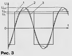
The amplitude of the first harmonic of the input voltage (curve 2 in Fig. 3) - Um1 = 1,27 Um, where Um is the amplitude of the pulses. The coefficient of 1.27 for other pulses the forms will be different, its values can be found e.g. in [2]. Current the voltage of the first harmonic U1 = 0,707Um1 = 0,9 Um, where Um = 1.1U1 Voltage at the output of the filter is smaller by the amount falling on the active resistance of the inductor, therefore, to operate the motor at rated speed Converter needs to generate rectangular pulses ("meander") amplitude Um=1,1·U1·Rd/(Rd+R1)=1,1·220·645/(645+ 17,6) = 236 V.
The correctness of the calculations was checked by computer simulation designed to filter using Electronics WorLWench. Derived from the model graph the output voltage (see curve 3 in Fig. 3) because of the presence in it not to the end of higher harmonics suppressed differs from that of the sine wave and corresponds to actually observed on the oscilloscope screen when the motor with filter.
In the manufactured filter as C1 and C2 were applied group United in parallel to obtain the desired capacitance of the capacitor KBG-MN, MBGC, MBGP, MBM for a voltage less than 1000 V (C1) and at least 400 In (C2). Choke from fluorescent lamp can be replaced by another close inductance, able to withstand without overheating consumed by the motor current. Homemade the throttle is harassed on a steel magnetic core USH 16x30. Its winding - 870 of turns of wire sew-2 is 0.3.
Practice has shown that the filter requires no configuration, and its consistent and parallel branches should be set independently. This will require a lamp filament 220 V, 75 W and AC voltmeter. As a "source signal", observing all the necessary precautions, you can use grid.
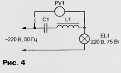
Sequential circuit L1C1 set up according to the scheme shown in Fig. 4. Lamp EL1 serves as a dummy load and at the same time the indicator settings. The source capacitance of the capacitor C1 charge is slightly less than the calculated. It gradually increase, parallel to the main connecting additional capacitors less capacity. The goal is to achieve the greatest brightness of the lamp or the minimum voltmeter.
The parallel circuit is set up according to the scheme shown in Fig. 5, achieving the lowest brightness of the lamp or a peak reading voltmeter.
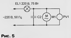
In time settings the motor shaft should rotate without mechanical load.
Literature
Author: Vladimir Volodin, Odessa, Ukraine


