


")

As a simple means to improve the quality of the received stereo of sound broadcasting programs, of interest to many hams. The author of the article analyzes the method of forming the frequency and phase characteristics of the radio and determines the units in which low-cost it is possible to introduce corrective elements to improve the selection signal at the output stereodecoder.
Quality stereo radio reception depends not only on real the ratio signal/noise at the antenna input of the receiver, but also on the decoding device. As you know, in stereodecoder (DM) integrated stereo signal (CSN) converted to a polar-modulated oscillations (PMC), and then at the weekend low-frequency signals of the left and right channels. Happening at the same time the transformation is determined, in particular, as important as transitional the attenuation between channels. Best channel separation allows to reach temporal decoding method, which excludes the recovery subcarrier and the associated non-linear and phase distortion. On this principle work most modern integrated DM.
The quality of the decoding is also significantly affected by input range KCC. Top of modulated frequency required for transmission of audio frequency in 15 kHz, when the stereo broadcast system with polar modulation (PM) and subcarrier 31,25 kHz is 46,25 kHz, while the system with pilot tone (PT) and 38 kHz subcarrier - 53 kHz. A mandatory condition is no distortion and good channel separation is horizontal (without obstruction) frequency response and linear phase response in nazionalnoi region frequencies, up to specified.
At the same time, the most typical is the receiver path having the AFC decay at higher frequencies, KCC.
This recession is formed due to the limited bandwidth of the tract FC and FM detector. If the cutoff frequency of the KCC on level - 3 dB denote the Fcp and the frequency subcarrier - Fпод, crosstalk between the channels can be calculated by approximate formula p=20 log (2 Fcp/Fпод).
It is easy to calculate that to obtain the separation of the stereo channels at 30 dB the required bandwidth of signals with the PM to 88 kHz, and signals with FRI - to 107 kHz. Of course, these data are approximate and do not take into account the peculiarities or another method of decoding. For correction of the frequency response curve in models of decoders apply certain correcting circuit, as a rule, a simple RC-type.
On the other hand, the excessive extension of the spectrum KCC leads to a sharp the increase in noise and interference from converting out-of-band signals. If the strip KCC is not limited to, the deterioration of the ratio signal/noise ratio when receiving remote stations can be 20 dB or more compared with mono regime. On the contrary: the narrowing of the band of KCC is an effective noise-reduction welcome.
The conflicting requirements to KCC in the best suited frequency response maximally flat up to a frequency of 70 kHz…80 with a further sharp decline, organized by the filters of high orders. This characterization allows to approach the maximum achievable specific parameters in diabetic and noise transitional fade between channels.
These provisions were confirmed in tests dvustennogo stereodecoder on the chip CRHA. In a typical switching circuit [1] on his the input applied to the simplest first-order LPF with a cutoff frequency of about 10 kHz. The decay of 6 dB/octave at frequencies above 10 kHz provides acceptable noise characteristics, but reduces crosstalk between the channels 43 dB (standard value without input filter) to 24 dB for signals with PM and 20 dB for signals with FRI. In addition, the filter is cut the upper part of the tone in region 10…15 kHz, which makes the sound "dull".
Overall, despite the progressive design solutions - temporal method channel separation with double sampling, additional suppression the pilot tone, etc.- mentioned DM worked worse than the decoder is outdated chip VA. Another drawback CRHA - nasty clicks in the audio tract when you turn on the stereo indicator. A replacement chip to another an instance of the fundamental changes brought.
To improve the quality of the proposed decoder is supplemented by the input filter of CIL forming the required frequency response with the capabilities of manual and automatic adjustments. The advantages of the new DM is also a separate indication system stereo broadcast, running silently.
Main technical characteristics
- Crosstalk between channels, dB, not less than.....34
- The ratio signal/noise in Stereo mode, dB.....50 70…
- The level of the input signal, mV......up to 150
- The transmission coefficient......1,2
- Current consumption, mA......7
Functionally, the device consists of three blocks (Fig. 1): input filter KCC, switch on a chip DD1 and decoder on a chip of DA1.
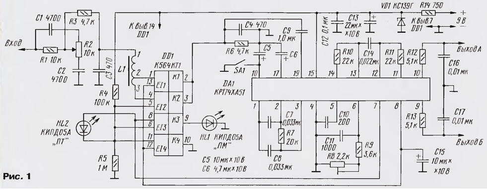
(click to enlarge)
Filter KCC is a further modernization of the device [2]. It parameters of advanced computer simulation - reduced ripple in tonal regions and increased the steepness of the cutoff in nazionalnoi. The filter consists of adjustable link R1,R2,C1,C2 and LPF 3rd order C3, L1, C4 with switchable in depending on the system stereo broadcast cutoff frequency. The frequency response of the filter - mode reception FRI (shown in Fig. 2).
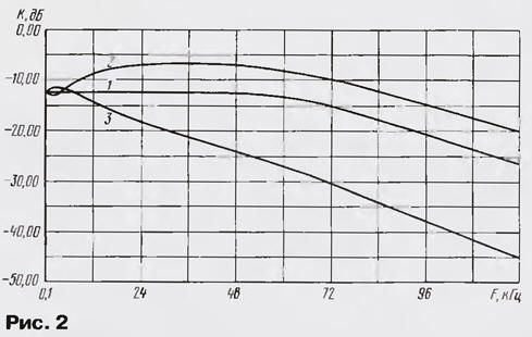
Link R1 ,R2, C1 ,C2 - bridge high-pass regulator KCC. Using the variable resistor R2, you can increase or decrease the level naturalnych (and partially tonal) components, resulting in a proportionate extension or narrowing the stereo due to the change of the transitional fade between channels [2]. In the middle position of the regulator R2 frequency response of the filter is horizontal up to the cutoff frequency (see Fig.2, curve 1), in two extreme positions - uneven its in the audio range does not exceed 2 dB. Adjustment captures only the top part of the sound spectrum above 10 kHz, which allows for consistent reception to emphasize the higher frequencies and thereby improve the sound quality.
Time changes and noise, it is minimal in the lower position of the engine resistor R2 when nazionalna part of KCC actually cut the sound close to mono. Thus, the adjustable element filter allows to obtain the adaptive quality of the output signal based on input from extended Stereo for high power RF signals to Mono - and noisy distorted, in particular, multipath reception.
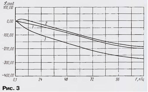
U-shaped LPF 3rd order assembles the elements of C3, L1, C4. This filter designed for the effective suppression of noise and interference from the conversion signals that lie behind the main information strip KCC. LPF synthesized the Design of the program MicroCap6.0. Its parameters are: cutoff frequency in the system with PT - 75 kHz in a system with RM - 60 kHz, the steepness of the decline in the transparency band - 15…17 dB/Oct, characteristic impedance 4.7 Ohm. The cutoff frequency structurally changed by switching the number of turns of the coil L1 e switch DD1. Thanks to computer modeling, the filter has a smooth frequency response (see Fig.2) and a fairly linear phase response (Fig. 3).
A filter connected to the KCC stereodecoder (DA1 chip) is a remote input circuit R1C1 [1]. The attenuation introduced by them (12 dB), compensated by a large margin amplification circuits DA1 (14 dB). When receiving signals from the PM on pin 8 chip DA1 is set to a logic low, close to zero. On control inputs 5 and 6 of switch DD1 has a high logic level, served with a middle point of the divider R4, R5. The key K2 on conclusions 4 and 3 is closed, the pin 3 of the coil L1 is connected to the capacitor C4. The filter is configured to the cutoff frequency of 60 kHz. Simultaneously open the switch RS and through his conclusions 8 and 9 the voltage readout from pin 7 of the chip DA1 is supplied to the led HL1, indicating that the mode is "PM".
In recognition of signals with FRI voltage level at pin 8 of the chip DA1 is changed to high, in fact, equal to the supply voltage. This signal is supplied to control inputs 12 and 13 of the keys K1 and K4 switch DD1. The Key K4, opening, reduces the voltage at the middle point of the divider R4R5 to low level. The keys K2 and KZ when it switches to a nonconducting condition, whereby the pin 3 of the coil is disconnected from the capacitor C4, and the led HL1 goes out. Simultaneously opens the switch SW1 which connects pin 2 of the coil L1 to capacitor C4. The inductance of the coil decreases, which leads to the restructuring of the cutoff frequency of the LPF up to 75 kHz. In addition, the cathode of the led HL2 is connected to the common wire via the open on pins 11 and 10 key K4, and its anode there is a voltage coming from pin 7 of the chip DA1. When this led HL2 indicates the mode of "PT". The switch SA1 is possible enforce the Mono. In this case both LEDs are extinguished, as the voltage at pin 7 of the chip DA1 will be absent.
Allowable voltage IC supply CRA - 2,7 7…V. Experimentally it is established that clicks when you turn the stereo indicator arise only when the supply voltage above 4 V. In this case, the voltage on the pin 15 of the chip DA1 is limited by the Zener diode VD1 at 3.9 V. the indicators HL1, HL2 included almost silently, the parameters of the chip remain high.
In stereodecoder used fixed resistors MLT-0,125, ceramic capacitors - type km, electrolytic import. The switch SA1 - button P2K. Variable resistor R2 is any compact, for example, SDR-4B, characteristic type A. due To the low voltage circuits DA1 emitters HL1, HL2 should have a high light output at low current. LEDs KIPDA satisfy this condition, but you can find other with maximum brightness, including imported ones. Coil L1 ferrite the ring CHH mm ferrite brand 2000NM. Winding 1 - 2 contains 110 turns winding 2-3 is 30 turns of wire sew 2-0,2. The quality factor of the coil is large, so the parameters of the LPF practically do not impair the resistance of the open channel of the chip DD1 (about 270 Ohms), in series with the coil L1.
Such nodes in the device as a filter KCC and switch DD1, settings need. In stereodecoder DA1 should only trimming resistor R8 to achieve sustainable recognition stereo "PM" or "PT" for inclusion the respective light-diode HL1 or HL2. After that check the work the adjustable link of the filter by rotating the handle of the resistor R2: the sound should to change from the expanded "Stereo" to "Mono". The subjective effect of this adjustment is well described in [2]. It is recommended to note the average position the regulator R2, which corresponds to a horizontal AFC CRA (see Fig.2] and normal Stereo mode.
The effectiveness of the LPF 3rd order easy to check, temporarily turning on the switch P2K (fixed button) for switching. When you click one group contact P2K should short pins 1 to 3 of the coil L1 and the other to disable the findings of the capacitors C3, C4 of the total wire. Disabling the filter by pressing button is accompanied by a sharp increase in noise and interference even when the reception is not very weak signals. Accept remote and weak signals in stereo mode becomes impossible at all. The inclusion of the LPF, on the contrary, cleans the signal from the noise, interference whistles, etc., with channel separation remains high.
In General, the quality of the proposed DM were significantly higher than source [1]. Filter KCC can certainly be applied to other decoders. Due to the relatively low characteristic impedance of the LPF, the output of which agrees well with the input of almost any DM. For odnomandatnykh DM switch DD1 is not needed and the circuit is greatly simplified (Fig. 4).
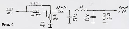
The number of turns coil L1 is chosen is $ 110 for the system stereo broadcast with MO or 140 for PM. However, for specific DM it is better to clarify experimentally. In this case the coil L1 is performed with several branches (10-15 turns) and when setting up switch them, achieving low noise and good separation of steroidal. This the work is best done while listening to the sound of stereodinamikami.
Literature
Author: A. Pakhomov, Zernograd, Rostov region