To negotiate a powerful output transistor with an antenna and filtering of the signal in most cases apply less sophisticated schematics:
- ferrite transformers that do not have filtering characteristics and are not accessible to Amateurs;
- P-loop, but cannot agree on the low output impedance of the transistor stage (2...15 Ohms) to the output impedance of the antenna, the loss in this case are great.
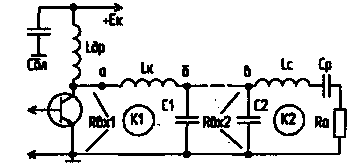
One effective solution to the problems is the T-loop, the principle of which is clear from Fig. 1.

Fig.1
From the diagram it is evident that this is a double-barrier system. The input impedance of the antenna (Ra) is introduced into the circuit K2. In this case the reactive component of the input impedance of the antenna can be easily compensated by changing the value of Lc, which is very important when tuning the antenna. The input impedance of the circuit K2 at point "b" when tuning into resonance.

It has a value around 100...2000 Ohms depending on the values Lc, which, in turn, is selected depending on the working frequency and power output of the cascade.
The collector of transistor operating as a current generator, connected in series in the circuit K1. Load circuit K1 (b) is the input impedance of the circuit K1 - Rвх2. To obtain the T-loop is sufficient to connect the points "b" and "C". The total capacitance C=C1+C2.
The input impedance of the circuit K1 at point "a" has a value

The presence of the two circuits in the diagram allows you to filter out unwanted components in the signal, the need for additional filters is eliminated.
Practically items are selected from the following formulae:
C [PF]=(8...20)L,
where L is the average wavelength in m.
With - the more, the greater the power, i.e., when P=10 W=8L, at P=200 W=20L. SR-a blocking capacitor DC voltage between the EC and the antenna.

where Rвх1, the load impedance of the transistor.
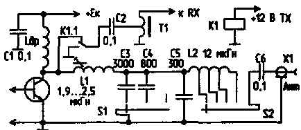
Practically running the scheme of the cascade ranges on 160, 80 and 40 m is shown in Fig.2.

The coil L1 has 16 turns of wire PESO to 0.5, the diameter of the frame is 16 mm, the winding length of 16 mm, tuning ferrite core with a diameter of 8 mm, length 20 mm, L2 contains 37 turns PESO-0,3, elbows - 25, 29 and 33 turns. The diameter of the Frame is 10 mm, the winding length of 12 mm. Coils are arranged so that between them there was no mutual induction: shielding, perpendicular axes of the coils.
S1 - switch ranges. Setup is as follows: with the switch S2, the connection to the antenna, and a core set L1 of the circuit in resonance to the maximum indicator of the antenna and the maximum collector current of the transistor. In General, the setup resembles the setup of the P-loop, but instead of variable capacitors or variable inductors and setting the maximum current of the transistor. Instead of L2 and S2 it is possible to use the Vario with the inductance 8...12 µh. Can setting in resonance to produce and use a variable capacitor, then the inductance L1 is constant and is 2.1 mH, but the tuning inductance, the author has shown great results, and the device turned out to be smaller in size than when using a variable capacitor.
When operating in the receive mode, the T-loop is an optional input band filter receiving device. Switch "the handover" by means of a relay K1 type RES-55A or the like. Transformer T1 is wound on the ring size HH mm with permeability 100... 1000 and contains 20 turns of wire PESO to 0.3 with a branch from the 5th loop, read from the grounded end (with input resistance of the receiver 75 Ohm).
Literature
Author: L. Ivanenkov (UA3LDW), Smolensk; Publication: N. Bolshakov, rf.atnn.ru


