


")

In such a broadband transformer winding is in the form of long two-wire transmission lines (based on coaxial cable or similar) wound on a ferrite ring. This embodiment of the winding virtually eliminates the leakage inductance and to reduce the inductance of the findings.
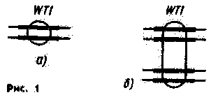
The symbol of the transformer on long lines (TDF) taken in the article, with one coil of a two-wire line shown in Fig. 1.and, with several (in this case two) are in Fig. 1.b.
In Fig. 2 shows the inclusion of TDF with transformation ratio n=1.
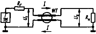
Fig.2
The transformer comprises a winding in the form of a homogeneous long line wound on an annular ferrite magnetic core. Its electrical length P=2пl/L, where l is the geometrical length of the line, L is the wavelength (lambda). As in the propagation of high frequency waves, the currents flowing through the conductors of the line, equal in value and opposite in direction, the magnetic core is not magnetized, which means that the power in the ferrite is practically lost. With approval of the ox new resistance line g with source resistances Rг and the load RL TDF is theoretically no lower and upper boundary frequencies. In practice, the maximum operating frequency is limited due to the inductance of the conclusions and emission lines.
You should pay attention to the peculiarity of TDF. which is the presence of two types of stresses: anti-phase U, the current between the conductors of the line and determine the signal power and in-phase (or longitudinal) V, due to the asymmetry of the load and dependent variants of inclusion of the transformer.
How is the common-mode voltage, the current between the generator and the load, i.e. the inductance of the line l b, can be clearly seen from Fig, 3.
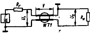
Fig.3
Obviously, the conductors of a long line shunt the load and the generator, if the flow of common mode currents. The introduction of the magnetic core increases the inductance of the winding, thereby increasing the resistance of the common-mode current and dramatically reduces their shunting effect. At the same time on the wave propagation, the magnetic circuit has no effect, as provided by the traveling wave mode
(Rг=g=Ri).
There are several ways of building a TDF with an integer ratio of p. for example, to adhere to the following rules. Winding (there should be n) is made equal to the electrical length of the segments of two-wire lines. Each winding is placed on a separate annular magnetic core of the same type. The inputs of the lines with increasing side connected in-series, with a reduction -- in parallel.
In General the scheme of inclusion of TDF with an integer ratio p is shown in Fig. 4.
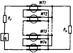
Fig.4
Here the balance right
Rг=n2Rн, U1=nU2, g=nRн.
In Fig. 5 shows various options for the inclusion of TDF.
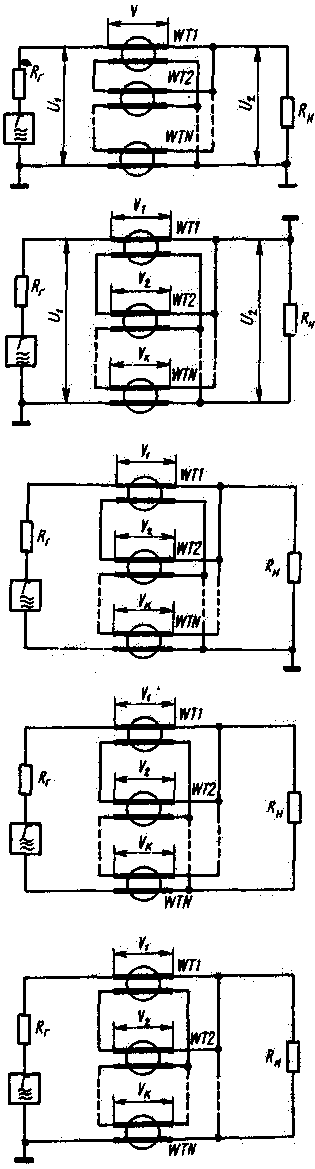
You can build a TDF and on the same magnetic circuit, but in this case, must comply with the following requirements. First, the number of turns of each line must be proportional to the value of common mode voltage, the current between the ends of this line, since the windings are linked by a common magnetic flux. Secondly, the geometrical lengths of all lines need to be the same. Depending on the inclusion of TDF may even happen that some lines are partially or completely should be placed not on the yoke.
To determine the number of turns in the windings, it is necessary to calculate the values of the common-mode voltage V on each line.
In TDF single-ended input and output (type NN. Fig. 5, a)
V K=(n-K)UN;
in inverting (type NN, Fig. 5, b) V K=(n-K+1)UN;
with balanced input and unbalanced output (CH, Fig. 5)
V K=(n/2-K)u n;
single-ended input and balanced output (type NS, Fig. 5, g)
V K=(n+1/2-K)UN;
with balanced input and output (type SS, Fig. 5, d)
Ve=(n/2+t/2-K)UN.
In the formulas, n is the transformation ratio, K is the ordinal number line, counting from the top, UN - load voltage.
These formulas are original. when determine the ratio of the number of turns in the windings placed on the yoke. If, for example, TDF with transformation ratio n=3 according to the scheme shown in Fig. 5, and, V1:V2:V3=w1:w2:w3=2:1:0. From this it follows that the top figure on the line is placed on the yoke fully (w1), second --only half of the windings (w2=w1/2) and the third (w3=0) must be the stump of the magnetic circuit. Geometric length of all lines are the same.
When reconciling "the wave channel" with the input resistance of 18.5 Ohm, 75-Ohm coaxial cable with TDF (included as Fig. 5, g) with transformation ratio 2 is the ratio of turns of the windings is equal to w1:w2= (2+1/2-1:(2+1/2-2)=3:1. This means that the upper magnetic core by winding pattern must be entirely, while the second - only the third part.
When the length of the lines for the windings is much less than the length of the working wave, TDF can be simplified: lines where the common mode voltage is equal to zero. replace the jumper. In this case, for example, three-winding TDF (Fig. 5, d) is converted into two-winding (Fig. 6).
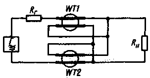
Fig.6
The transmission coefficient of TDF depends on how impedance is different from the optimal values and what is the ratio of the electrical length of the line and the wavelength. If, for example, is not correct twice the number of losses in TDF is 0.45 dB length of lambda/8 and 2.6 dB at lambda/4. In Fig. 7 shows the dependence of the transmission coefficient of TDF with n=2 from the phase of the lengths of its lines for three values of g.
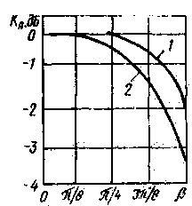
Fig.7
The calculation given in [4], shows that if lines are used to optimum values, the standing wave ratio in TDF does not exceed 1,03 length of lambda/16 and at a length of 1.2 lambda/8. Hence we can conclude that the parameters of TDF remain satisfactory with a length of two-wire lines is less than lambda/8.
Original data in the calculation of TDF are the transformation ratio n, the option to include TDF, the lower and upper bounds of the operating range of frequencies (in Hertz), the maximum power Rmah at the load (in watts) load resistance RL (in ohms) and the impedance of the feeder g (in ohms). The calculation lead to the following sequence.
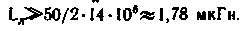
1. Determine the minimum inductance of the conductor lines l b (Henry) from the condition that
Lд>>Rг/2fн.
In practice, l b, it is possible to take in 5…10 times the calculated relationship Rг to 2fн.
2. Find the number of turns w line on the ring of the magnetic circuit:
where dcp - the average diameter of the ring (in
cm), S is the cross - sectional area
the magnetic core (in cm2), u is the relative magnetic permeability of the magnetic circuit. 3. Calculate the common mode current Ic;
(in amperes) flowing through the winding of TDF, the lower the operating frequency:
Ic=Vc/2пfнLл,
where Vc is the common mode voltage on the line, calculated for specific options for inclusion in accordance with the above ratios.
4. Determine the magnetic induction (in Tesla) magnetic circuit:
B=4*10-6.uIc/dcp.
The magnetic core is selected based, that he had not filled in-phase current (or constant, if there is one). For this purpose, the magnetic induction in the magnetic circuit must be an order of magnitude less than the saturation induction (taken from reference).
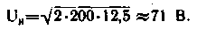
5. Find the Peak voltage Uпик in line:
where is the CWS in the feeder.
6. Calculate the effective value of the current Eff (in amperes):
7. Determine the diameter d of the wires (in millimeters) long line:
where J is the allowable current density (in amperes per square millimeter).
For TDF antenna matching devices are suitable ring (sizes CHH, CHH) the magnetic cores made of ferrites US, VS, WS, VS and with permeability of 400, NN, NN. If necessary, the magnetic core may be composed of several rings. The desired characteristic impedance of a long line get, uniformly twisting each other (with a certain step) conductors (see table). In the case of cross connection of wires is lower than when interconnected adjacent conductors. Characteristic impedance of the line from non-twisted wires with a diameter of 1.5 mm was 86 Ohms.
Characteristic impedance of a long line depending on the pitch and type of connections
View
The pitch, cm
4
3
2
1
0.67
0.25
:
70
60
56
44
36
-
I I
45
43
40
33 (32)*
-
-
X
23
22
20
18 (19)*
-
10**
* If the diameter of the wires 1 mm.
** If the diameter of the wire 0.33 mm.
To improve the parameters (in particular, skewness) and simultaneously to simplify the design of matching-transforming node, apply the serial connection of several different types of TDF.
For example, in the above method we calculate composite TDF with n=2. He must coordinate the input impedance of 12.5 Ohm balanced antenna with coaxial cable RK-50. The lower operating frequency is 14 MHz. Power does not exceed 200 watts. For TDF intend to use the magnetic circuits of size CHH (dcp=3,65 cm, S=0,7 cm2) of ferrite NN (its specific induction of saturation - 0,44 T/cm2 [5]).
Let the first stage of the transformation ratio n=2 compound of TDF (Fig. 8) will be included in the scheme Fig. 5, and the second (n=1) -according to the scheme of Fig. 5,
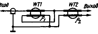
Fig.8
Expect first TDF.
1. Find L B:
Take l b is 13.5 µh.
2. The calculated number of windings:
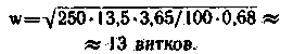
The number of turns of the double thick wire barely fits in the window of the magnetic circuit. It is therefore advisable to use two rings. In this case, the magnetic circuit will have dimensions CH H (S=1.4 cm2). New number w:

3. Determined by the peak voltage at the load:
4. Find the common-mode voltage on the windings in accordance with a switching circuit (Fig. 5, a):
V1=(2-1)71=71 V. Since common-mode voltage on the other winding is equal to 0, this coil is replaced by a jumper (Fig. 6).
5. Common-mode current is equal to:
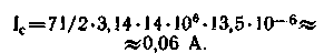
6. The calculated magnetic induction in the magnetic circuit:
In=4*10-6*100*9*0,06/3,65=59*10-6 TL, much less than the saturation induction.
Characteristic impedance of the line g1=50 Ohms.
In the second TDF is appropriate to apply the same ring, as in the first. Then l b=13,5 mH, w=9 turns.
7. Common-mode voltage on the winding V=(2+1/2-1)71=106,5 V.
8. Common-mode current is equal to:
L=106,5/2*3,14*14*106*13,5*10-6=0,09 A.
9. Magnetic induction
In=100*4*10-6*9*0,09/3,65=89*10-6 TL.
And in this case it is less than the saturation induction. Characteristic impedance of the line winding choose about 12 Ohms.
The diameter of the wires for the lines of TDF is determined as the diameter of the wire for winding in conventional transformers. This calculation is not presented here.
The attentive reader may notice a discrepancy in the calculation (associated with the use of a compound of TDF). It lies in the fact that the inductance l b is calculated without taking into account the fact that the winding of TDF first and second stage are connected, i.e., with some margin. So in practice, at each stage of TDF can reduce the number of turns in the windings and to apply ferrite cores of smaller size.
Using a combination of different single TDF, you can get a wide range of TDF with desired characteristics [4].
I made TDF should be measured in efficiency and asymmetry factor [4]. The scheme of inclusion of TDF in determining the first parameter shown in Fig. 9, second - in Fig. 10. Loss (in decibels) in the transformer is calculated by the formula: a=20lg(U1/nU2).
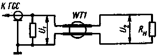
Fig.9
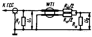
Fig.10
The author made several of TDF. Practical data some of these are listed below. The appearance of two transformers shown in Fig. 11.

Fig.11
Balun TDF (type NS) with transformation ratio n=1 operating in the frequency range 1,5… 30 MHz with output power up to 200 W, for coordination of feeder RC-50 with an input impedance of antenna is 50 Ohms can be made on the yoke VS size
CHH. The number of turns of the windings of the line (g=50 Ohm) - 9. Winding 1-1', 2-2' (Fig. 12) 2 shakes of wire sew-2 1,4 bifilar, without twists. To ensure a constant distance between the wires, they wear Teflon tube. The winding 3-3' is wound separately on the free part of the ring the same wire and the same length as the winding 1-1', 2-2'. Efficiency made of TDF was about 98%. the coefficient of skewness of more than 300.
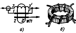
Fig.12
TDF with transformation ratio n=2 (type NS), designed for power up to 200 W, a matching 75-Ohm characteristic impedance of the feeder with balanced input antenna whose input impedance 18 Ohms. can be made on the yoke NN (Fig. 13) the size CHH. Winding must contain 9 lines turns of wire sew-2.1,0. Made transformer had an efficiency of 97 %, the asymmetry factor at a frequency of 10 MHz to 20, at a frequency of 30 MHz is at least 60.
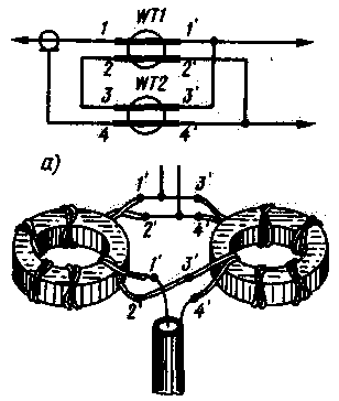
Fig.13
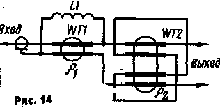
In Fig. 14 is a diagram of an inclusion compound of TDF (type NS) with transformation ratio n=3, matching the antenna with the input resistance 9 Ohm, 75-Ohm coaxial cable. TDF, designed for operation in the range 10…30 MHz at a power of 200 W, to perform on the rings (size KHH) of ferrite VS. The magnetic cores of transformers WT1 and WT2 are two rings, windings and the coil L1 must contain 6 turns. Long lines and coil perform wire sew-2 to 1.0. Characteristic impedance of the line for WT1 - 70 Ohms, for WT2 - 25 Ohms. Constructed of TDF had an efficiency of 97 %, the coefficient of skewness of at least 250.
Before use of TDF should take measures to protect them from adverse climatic effects. The transformers are wrapped with Teflon tape, placed in a box and, if possible, pour the compound KLT.
Literature:
1. Key to 3., Libyan E. Amateur antenna short and ultrashort waves.- M.; Radio and communication, 1983.
2. Rothammel K. Antenna.- Moscow: Energiya, 1979.
3. Zakharov V. three-element Triband antenna wave channel.- Radio, 1970. No. 4.
4. London S.E., S. tomašević, V. - Handbook of high-frequency transformer devices.- M.; Radio and communication, 1984.
5. Mikhailova M. and others soft Magnetic ferrites for electronic equipment.- M.: Radio and communication, 1983.
Author: V. Zakharov (UA3FU), Moscow; Publication: N. Bolshakov, rf.atnn.ru