When working on УSW device approvals are rare. This is because typically uses a matched resonant antenna.
But there are times when the farm ham there is no cable with the required characteristic impedance. Not even always in the range УSW impedance of the antenna is equal to its theoretical value, especially when it is irrational install. Fix it with the help of matching device that УSW range constructively handle simply. The simplest matching unit (SU) is a common P-loop (Fig.1).

When the capacitance of variable capacitors 2...15 pF and the coil containing 2 round wire with a diameter of 1 mm, wound on a mandrel with a diameter of 10 mm, and the distance between the turns of 5 mm and the length of the coil leads 15 mm (not more), it SU allows you to reconcile the active on-load from 30 to 300 Ohms with a transmitter having an output impedance of 50 Ohms or 75 Ohms. In this case the agreement with the cable 50 Ohm load from 30 to 100 Ohms the efficiency of the device was not less than 80%, during the negotiation of the load from 100 to 300 Ohm - no worse than 60%, during the negotiation of the load from 10 to 30 Ohm - no worse than 50%. This SU has in LW ranges from 1.8 to 50 MHz the SWR is not worse than the 1.2.
Thus, using this SU directly at the antenna operating in the LW range, this antenna can agree on and work on 144 MHz, when changing the matching mode in the range of SW. This gives you the opportunity to use the available LW antenna for operation at УSW, which saves cable. Especially good approval can be obtained by using two matching devices: one directly at the antenna and another at the output of the transmitter.
When using SU (Fig.1) for matching the transmitter output to the power cable of the antenna is able to negotiate the transmitter with the cable, but is not always possible to get approval of the cable with the antenna when using SU directly on the antenna (of course, that is not designed to work at 144 MHz). This is because the impedance of the antenna can have a large reactive component in УSW range, and SU (Fig. 1) effectively coordinate only active constituents.
This problem can be solved quite simply. The first thing to do is to slightly change the number of turns in the coil SU - it can be from 1 to 5, a diameter of from 5 to 15 mm and the distance between turns is 1 to 7 mm.

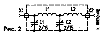
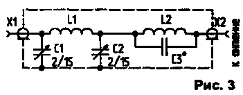
Very efficient also the inclusion of the inductance at the output of the SU (Fig.2). Additional coil contains from 2 to 5 turns of wire with a diameter of 0,8...1,5 mm. in diameter from 5 to 15 mm, the distance between the coils - 2...7 mm. Usually, by varying the coil and coil P-outline, almost any antenna can be configured for operation in the 144 MHz band. Sometimes, in the most difficult cases, permission may need to include the output of a P-circuit capacity 10... 50 pF (variable) (Fig.3).

Parallel capacitance is a choke (10 turns of wire PEL-1, the mandrel 10 mm, the distance between the coils is 1 mm), which has no resonance with this capacity in the 144 MHz band and having a low resistance on SW. When you configure LW antenna for operation in the range УSW you can get a false setting when the system will be equal to 1, but the antenna will not radiate. Well, if the radio has a simple field strength indicator. Using it, it is advisable to compare the field strength generated by the antenna, the control УSW antenna - pin 50 cm long, connected to the output of this matching device is configurable SW antenna.
It should be noted that long LW antenna-dipoles, slavery and especially antenna having a non linear configuration form, such as frames, create a rather complex pattern on УSW with many petals, but the difference between the maximum and minimum field strength generally does not exceed 10 dB.
All the SS were made in carefully soldered the case of two-sided foil fiberglass, used air capacitors from old УSW radio stations, all connections were minimal length. When using SU directly on the antenna it is necessary to take measures a moisture barrier. Although the CWS SU (Fig.1...Fig.3) in the LW range is small, their use may still shift the resonant frequency of the antenna operating in top LW bands, especially shortened.
This will require additional tuning these antennas is in the range of SW. You should also pay attention to the fact that some of the LW antenna ranges according to their design features can't be used to work on 144 MHz, due to the fact that their entrance fundamentally nesoglasen in the range УSW, for example antenna with gamma-approval of the extension coil and some other types of antennas.
Matching device, shown here, is operable throughout the range of 144... 146 MHz.
Author: I. Grigorov (RK3ZK), Belgorod; Publication: N. Bolshakov, rf.atnn.ru


