


")

In reproducing or receiving equipment sometimes appear narrowband interference or crosstalk, for example, a network. How significantly to weaken, says the author.
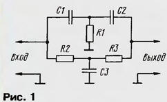
For the most effective noise rejection filter. It suppresses the interfering signal and passes the remaining signals. As customizados element in it is most often used double T-shaped filter or the Wien bridge. As shown, a simple and reliable device is in uses a double T-shaped filter (Fig. 1) because it can make the passive. In this embodiment, signals with a frequency above registeremail pass with low loss through the chain C1R1C2, and below - in R2C3R3. Signals same with registeremail frequency pass through both chains are becoming opposite phase, cancel each other out at the output and significantly weaken.
If you want a filter with tunable notch frequency device have to be difficult, because you need to synchronously change the settings at least the three elements. Easier to collect another filter (Fig. 2), known as differential-pavement (see, e.g., Horowitz P., hill, The Art circuitry. - M.: Mir, 1998, p. 296), which has the same frequency properties. All capacitors must be the same capacity, and the resistance resistor R1 is six times greater than the resistance of the resistor R2.
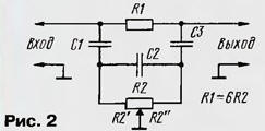
A distinctive feature of this filter is the ability to change the notch frequency one variable resistor. The tuning frequency of the filter is determined by the formula Fpeж= 1/2·Cv3R2' R2", where R2' and R2" is the resistance of the left and right (under the scheme) parts of the variable resistor, respectively; C is the capacitance of each capacitor.
On the basis of this chain you can perform the notch filter with acceptable parameters (Fig. 3).
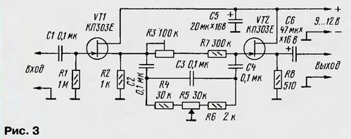
To exclude the influence of the signal source and the load the filter options on the input and output chains set of buffer stages field-effect transistors. These on the diagram the values of the filter elements can rebuild in the frequency range 30… 120 Hz variable resistor R5. The adjusted R2 resistor to achieve the maximum suppression registerimage signal.
In Fig. 4 shows the experimental frequency response of the filter for the two frequency settings - 50 Hz (1) and 100 Hz (2). The total attenuation of the device is 6…7 dB, and the relative attenuation at the frequency settings - 40…43 dB. In other words, the signal interference in relation to the useful signal is attenuated at least 100 times. AFC filter near the frequency of rejection has smooth slopes.
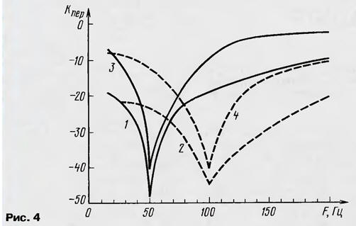
The steepness of slopes can be significantly increased (curves 3 and 4) if the engine resistor R5 to disconnect from the common wire and connect to the source of the transistor VT5. In this case, decrease the loss in bandwidth and the depth of rejection.
To change the tuning frequency of the filter, you need to install the capacitors C2 - C4 other capacity - it is calculated according to the above formula.
Also indicated in the diagram, it is permissible to use transistors CPA, CPB. Capacitors C1 - C4 - K73 series or similar, and capacitors C2, C3, C4 must be picked up the same capacity with an accuracy of a few percent; C5, C6 - series K50, K52, K53. AC and rigged resistors - SP, CPF, JS4, constant - MLT, S2-33.
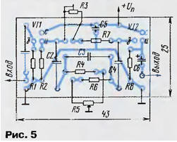
Most parts are placed on a printed circuit Board (Fig. 5) of one-sided foil fiberglass, which is then set in a metal or a metallized plastic housing of a suitable size. Metal or metallization of the housing is connected to the common wire. Variable and trimmer the resistors are placed on the front wall of the housing.
The maximum input voltage for this filter is approximately 1 V. To to increase it, you need to replace a source of repeaters amplifiers to apply to OU - each of them must be reinvestiruet with a transfer ratio of 1.
For stereociliary need to make two filters and install a separate variable and adjustable resistors, since the dual resistors will make misalignment and simultaneously adjust the frequencies of the filters will be ineffective.
Author: I. Nechaev, Kursk