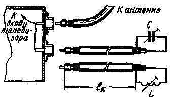
To eliminate these drawbacks by enabling the cut end of the cable to a variable capacitance or a variable inductance.
To suppress harmonic noise in the frequency ranges 1-12 of television channels can be used for virtually all types of coaxial cables. When used for tunable filters of segments of coaxial cables with polyethylene filler (e=about 2.2-2.8) and a characteristic impedance r=75 Ω (RC-1, RC-3, RC-4, RC-8, RC-20, RC-49) the lengths of these segments, as well as the minimum and maximum capacities of trimmer capacitor (Cmin and Smaks) and inductance tuning coil (Lмин and Lмакс) is shown in table. 1.
Channels
Filters, tunable capacitance
Filters, tunable inductance
The length of the segment cm
Smin, pF
Smaks, pF
The length of the segment cm
Lмин, MH
Lмакс,MH
1
64
15
32
130
0,22
0,70
2
55
13
25
110
0,17
0,56
3
43
10
18
86
0,15
0,36
4
39
9
16
78
0,13
0,32
5
36
8
14
72
0,12
0,26
6
20
4 8
6 3
49
0,067
0,12
7
19,5
4 6
6 0
39
0,062
0,115
8
19
4 4
5 7
37
0,060
0,11
9
18
4 2
5 5
36
0,057
0,105
10
17
4 0
5 3
34
0,055
0,10
11
16.5
3 9
5 1
33
0,053
0,097
12
16
3 8
4 9
32
0,051
0,094
In the case of coaxial cables with polyethylene filler (e=2,2-2,3), but a characteristic impedance r' not equal to 75 Ω (RC-2, RC-6, RC-19, RC-48, РSW), the required length of the segments of cable television channels 1-12 are equal are given in the same table, and the minimum and maximum values of capacitance or inductance should be calculated by the following formulas:

Tunable bandstop filters must be enabled in parallel to the antenna of the television receiver. Structurally, the filter is made in the form of a segment of the cable to one end of which is attached television antenna plug and connected to another trimmer capacitor or coil with variable inductance (Fig. 1).

Fig.1
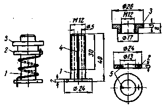
Coil design variable inductance is shown in Fig. 2. The coil form is made of organic glass and consists of two separate parts - 1 fixed and movable 2. The stationary half is threaded for screwing the nut 3. The change of the coil inductance is due to the change of the winding pitch when unscrewing or screwing of the nut.

Fig.2
To prevent rotation of the movable half of the frame upon rotation of the nut on the fixed half made a groove 4, which goes to pin 5 inserted in the movable half. Since the change of length of the coil during unscrewing of the nut is only due to the elastic condition of the turns of the coil, winding coil, it is desirable to use a bronze wire with a diameter of 1 mm.
Coil data coils for different television channels are given in table. 2.
Channels
1
2
3
4-5
6-12
The number of turns
7
6
4,5
4
2,5
To enable the segment of the cable parallel to the antenna in TV, which has only one antenna connector, you need to install the second one and include it in parallel with the main. The TV has two antenna sockets, one of them can be used to enable the segment of the cable. To do this, from the nest, not used to activate the antenna, it is necessary to unsolder the parts and connect this Jack in parallel with the used. In the absence of noise, the filter must be disconnected from the TV, as it weakens the useful signal.
When you need to attenuate the harmonics emitted by the SW transmitter, tunable band-stop filter is soldered directly to the antenna feeder (see "Radio", 1961, No. 7). As is usually the fundamental frequency of the transmitter is much lower than the resonance frequency of the filter, it almost does not consume useful transmitter power and no need to turn it off. Sections of cable filters connected to the transmitters need to have a high operating voltage, as may occur when you configure the filter resonance possible breakdown voltage cable insulation.
Author: N. Semenyuta; Publication: N. Bolshakov, rf.atnn.ru


