they require to switch momentary energizing of working winding. In addition, using these relays to improve the reliability it is useful to include both parallel groups of contacts. The voltage on the relay is energized from the power supply of the amplifier.
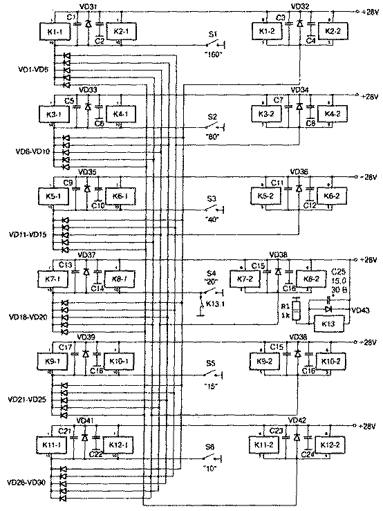
Upon initial turn on of the power supply unit of the power amplifier through the normally closed contacts K13.1 relay K13 (Fig. 1) closed circuit litany "working" windings of relays K7-1 and C8-1.

Fig.1
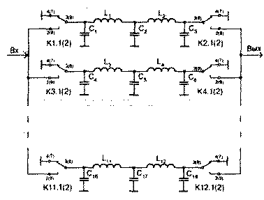
The contacts of relay K7.1(2) and K8.1(2) connect the LPF 20-meter band to the output of the power amplifier and the matching device (Fig.2). Simultaneously through diodes VD16-VD20 is powered on "pneumatic" winding K1-2,... K6-2, K9-2, ... K12-2 relays of the other bands (Fig. 1), which leads to shorting on the case of the LPF of other ranges, as shown in Fig.2.

Fig.2
In series with the relay coil K13 included the resistance of R1 in parallel across the relay coil - electrolytic capacitor 15,0 UF. The capacitor is charged, relay K13 and de-energizes the contact K13.1 working windings 20-meter band and "pneumatic" other winding.
When you move to another range, press the corresponding button S1-S6. This closes the power circuit "working" windings of the selected range, and through the diodes - "pneumatic" winding of the relay of the other bands. The current through the relay occurs only at the time of pressing the buttons S1-S6 to the operation of certain relays.
At the input of the LPF relay contacts connected in parallel (Fig.2). The output of one group can be used for switching light diodes indicating the enabled range.
Details
As VD1...VD30 applied diode assemblies KDA, which allowed to reduce the dimensions of the PCB. VD31....VD42 - CD or similar. Instead of relay SRU-32 you can use CPF-20. Relay K13 - RES, operating voltage 12-18 In, you can use other similar relays. Blocking capacitors C1...C24 0.01-0.1 μf, at a working voltage of not less than 40 V.
All configuration of the switch is to set a resistance R1, to force the 20-meter band after power-up.
Switch LPF amplifier works with transistors with an output of about 250 watts. The LPF is performed according to the standard scheme and configured using the meter response.
Author: Nikolai Kononov (RW6HW), Stavropol, Russia; Publication: N. Bolshakov, rf.atnn.ru


