


")

Receiving paths of different equipment (radios, audio players, CB transceivers, etc.) contain such nodes of the same type as amplifiers audio frequency (3H), amplifiers intermediate frequency (if) FM and AM stations. Their have to check when repairing equipment in the first place. This will help offer here the probe generator.
This relatively simple device provides for the formation of control signals 3H frequency of 1 kHz and the modulated signals to the if frequency of 10.7 MHz and 465 (or 455) kHz. The amplitude of each signal can be adjusted continuously.
The basis of this apparatus (Fig. 1) - generator of transistor VT1. The operating conditions set the switch SA1. In shown in the diagram position ("3H") switch the supply voltage of the battery GB1 is supplied through a resistor R9 to transistor and the generator starts at a low frequency. It is defined castorocauda chain R2C3R3C4R5C5 in the feedback circuit of the transistor.
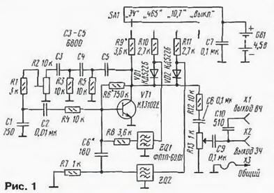
In the switch position "465" supply voltage on the transistor enters through the resistor R10, which opens the diode VD1 and the feedback circuit transistor cascade filter included ZQ1. Generated at frequencies 3H (1 kHz) and FC AM (about 465 kHz), simultaneous modulation of the if signal the 3H signal. Filter R1C1 eliminates feedback at a high frequency through the capacitors C3-C5, ensuring stable operation of the generator to the inverter.
When the switch is set to "10,7", the supply voltage on the transistor flows through the resistor R11. Opens the diode VD2, and in return path connection turn on the filter ZQ2. The generator will operate at frequencies 3H (1 kHz) and FC FM (about 10.7 MHz). The if signal premodulated signal 3H.
Generated signals via a resistor R12 and capacitor C8 is coming to the regulator output voltage R13, and with its engine - output jacks on X1 and x2.
In the switch position "Off" the power source is disconnected from the generator.
Except as described in the diagram, the device can be applied to the transistors CTA-CTD, CTU. Filter ZQ1-any of a series of PPP-60, more better narrow-band. Frequency of 455 kHz, you must use a filter foreign production. Filter ZQ2 - piezoceramic strip at a frequency of 10.7 MHz, domestic (for example, PPP-0,49 (a) or a similar import. Capacitors - K10-7, K10-17, CCL or small import. The trimmer R2 - SDR-1B, AC R13 - STRs JS4,the rest of the IFL, C2-33. Switch - any small in one direction and four (or more). Source power - voltage 4.5… 12 V. It can be connected in series galvanic cells, batteries, battery "Krona" or a verifiable source design.
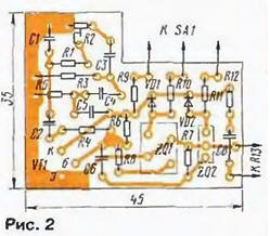
Most parts are placed on a printed circuit Board (Fig. 2) of one-sided foil fiberglass.
It is placed in a plastic housing the right size, at which the set variable resistor R13, sockets X1, x2 (Fig. 3).
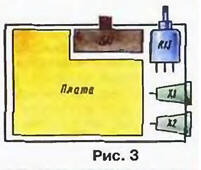
In one of the nests, depending on which nodes check insert the dipstick. Common wire out through the hole in the casing and provided with clamp "crocodile". In the case where the power source built in, you need to provide for him a place in the housing. The installation of capacitors C7, C9, C10 performed by surface mounting.
Instead of the filter on the frequency of 465 kHz is possible to put a filter at 455 kHz then the generator will operate at this frequency. It is permissible to use the switch on five points and additionally enter that frequency. The new filter should include as ZQ1. If you plan an external power supply, a new frequency can to install, using the released switch contact.
To configure the device you need at a voltage with which it will work. Current consumption is in the range of 0.5-3 mA depending on supply voltage.
The establishment of the probe oscillator start by defining the mode, DC. To do this, in switch position "10,7" and lower on the diagram the position of the slider the R2 resistor selection R6 install the collector of the transistor approximately half of the supply voltage. In the case of oscillation at the frequency significantly below the 10.7 MHz (spurious channels bandwidth filter) capacity capacitor C6 should be reduced. If generation do not, then the capacity of this capacitor and the resistance of the resistor R7 should be increased. Control generation with an oscilloscope (or frequency counter), connecting it to General the wire and Jack.
Then check the generation in the switch position "465" (or "455") and moving the slider to the resistor R2 to achieve stable generation of 3H and HR signals at positions of the switch "465" ("455") and "to 10.7". If you are in position "3H" generation of unstable, have to pick up the resistor R9.
The probe is used as usual, feeding the signals at certain points check device.
Author: I. Nechaev, Kursk