


")

There are many probes that hams use for quick checks at the time of establishment of radio equipment. The proposed variant of the original, that contains in one housing two designs - the AF signal generator and amplifier such signals, which significantly expands the possibilities of this "measuring the device".
When building and repair sound amplifying equipment often apply the AF signal generators, And in most cases, it helps to have generator with fixed frequency is about 1000 Hz. It can be in the form of the probe or the probe. Such structures were described in [1-4].
There are cases where, in addition to the generator AF required a simple amplifier, to check the availability of the signal, say, the output of the detector, pre-amp, etc. With it, you can also define a cascade, making a strong distortion, or cascade with a very small gain.
That's why I decided to develop a probe that includes both devices (Fig. 1). It is powered from the tested design, so the range supply voltages listed on the schematic is very broad. Of course, not excluded the option of using an independent source, say, a voltage of 6 V.
The oscillator frequency CC is chosen to be 1000 Hz, the amplitude of the output signal at the probe the probe can be in the range 0…1 V. the sensitivity of the AF amplifier is 50 mV.
The probe contains a node voltage, the oscillator and the amplifier AF. In your site stabilization is the VD1 diode protects the tester from incorrect feeding voltage reverse polarity. On the VT1 transistor and diodes VD2, VD3 is made the generator current, and the Zener diode VD4 and the transistor VT2 - stabilizer voltage. Connected to the output of the stabilizer HL1 led signals the voltage supply to the oscillator and the amplifier.
On the elements DD1, DD2 assembled the generator of rectangular pulses [3], which then "smoothed" to sinusoidal oscillations of the primary winding (more number of turns) of the transformer L1. Since the secondary winding (small number of turns) the signal is sent to a group of contacts SA1.1 switch SA1. In the diagram shows the position of the contacts corresponding to the mode "Generator", the signal continues on variable resistor R6 (the amplitude regulator the output signal of the probe), and with its engine - on emitter follower, performed on the VT3 transistor.
With the load resistor repeater R8, the signal continues on into the amplifier (transistors VT4-VT6). Diodes VD5, VD6 prevent distortion type "step", the resistor R10 helps to zastabilizirovat mode transistors DC. The amplifier output is connected by the contact group SA1.3 either the stylus X3, either to the dynamic head of BA1 (when the movable contact is in lower scheme).
If you want to use the generator, the switch is installed in shown in the diagram position, and the feeler XS relate to the findings of the details check the cascades. Signal flow check by oscilloscope or by ear.
When necessary, the amplifier, the handle of the switch is moved to another position. Probe XS also relate to the findings of the details, and sound in the control head the presence of a signal CC and its passage through the cascades radios.
Also indicated in the diagram, it is acceptable to use in place of transistors VT2 CTG, CTA; the remaining transistors - any of the series KT361, CT (VT1), KT3102, KT315 (VT3, VT4), KT815, CT (VT5), CT, CT (VT6). Diode VD1 - any of the series CD, CD; VD2, VD3, VD5, VD6 - series KD521, CD. Zener diode VD4 - KS147A, XG, XA, XG. Led - any of a series of AL307. Instead CLA will work CLA, CLE.
Variable resistor R6 JS2-3, others - MLT-0,125. Capacitors - any compact and oxide - for a rated voltage of not lower than specified in scheme. Switch - slide from domestic or foreign radios. Dynamic head - any small power of 0.1-0.5 W with sound - Cova coil impedance of 4-16 Ohms. If the design run, as the author, the form of the probe (Fig. 2), it is better to apply the dynamic head from Chinese electrified toys. It is of small dimensions (diameter: 27, height 9 mm), output power is 0.1 W, the resistance is 8 Ohms.
The transformer is wound on a ring CHH ferrite NN and contains 250 turns of wire sew-2 0.2 s withdrawal from 230-turns, starting from the left on the output circuit.
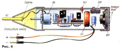
Most of the components mounted on the circuit Board (Fig. 3) size h mm fixed inside the cylindrical body (Fig. 4). During installation chips should be available conclusions 1,2,8 to connect a common wire. Dynamic head is glued to the end cap, which drilled hole. Variable resistor is installed from the side of the stylus X3, its axis is in tapered tip and squeezed it with epoxy. Turn the ferrule relative to the housing install the necessary level of the output signal probe or sensitivity of the amplifier.
Of course, another suitable body, such as rectangular, which can to install a conventional dynamic driver. Then the do probe and remote connect him with the details of the probe with shielded wire (screen fluster to minus power).
When establishing a probe selection resistor R5 sets the oscillator frequency approximately equal to 1000 Hz, and the selection of resistor R7 achieve this mode of operation transistor VT3, wherein the signal generator is supplied to the stylus XS, not distorted even at upper circuit on the position of the slider of the variable resistor.
Literature
Author: I. Patchin, Fokino Bryansk region.