


")

One of the types of generators of sinusoidal oscillations is used to specify the frequency of the RC-elements. These generators are quite complicated, require special measures to stabilize the amplitude of oscillations and do not have high stability frequency.
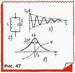
Safer and generators work better with parallel oscillating circuit in as customizados element - often called LC-generators. Recall that the parallel resonant circuit comprises a capacitor and a coil the inductance. If a charged capacitor is connected to the coil, then in the resulting contour (Fig. 47) damped oscillations occur. Their frequency is determined by the Thomson formula: fo = 1/2π(LC)1/2.
The oscillations would continue indefinitely, if in the circuit of energy loss, for example, on the active resistance of the coil wire. In addition, some. let and a small proportion of energy to give to the load generator!
The less energy loss, the higher the factor of the circuit, equal to the number vibrations to the point of reducing their amplitude example but 10 times. This little fact who knows. Loss of contour in the condenser is usually small compared to losses in the coil, so the factor of the circuit is almost equal to the quality factor coil, defined as the ratio of reactance of the coil to active.
The quality factor of RF coils bands LW, MW and LW should usually 30…300, depending on size and quality of execution. Large coils wound for bands LW and ST special stranded wire (LSSO - Litz wire) or thick silver plated wire for the range of LW, have usually and more efficient.
To significantly reduce the dimensions of the coils while maintaining a high q allow the cores (cores) high frequency ferrite or other magnetodielectric (magnetite, occifer, carbonyl iron). However, when the use of such coils in the generators need to pay attention to temperature dependence of magnetic properties so as not to impair the stability the frequency of the generator.
The factor of the circuit and determines the width of the resonance curve. It characterizes the dependence of the amplitude of oscillations in the circuit when the frequency excitation from an external source of sinusoidal oscillations. Link source outlined to obtain the correct results should be very weak at the coincidence frequency oscillation source with a resonant frequency of the circuit the oscillation amplitude to a maximum, and when the detuning is reduced. Width the resonance curve at the points where AMS!itude falls to 0.7 (3 dB), back proportional q: 2Δf=f/Q (Fig, 47).
The basic idea of constructing generators with LC-circuit is as follows: decrease energy in the circuit oscillations in the amplifier needs to be filled element driven from the same circuit in accordance with Fig. 44. When this should be performed two conditions: amplitude balance and balance phases.
The first condition requires that the energy supplied to the amplifying circuit from item is exactly equal to the energy losses in the circuit and in connection with the circuits load. With a weaker feedback damped oscillations and generation stops when a strong - amplitude increases and the amplifying element either in the restriction mode, when the voltage generated the stabilization circuit amplitude. In both cases, the gain is reduced, restoring the balance of amplitudes.
The balance of the phases is that the vibrations from the amplifying element is supplied to the circuit in phase with his own. Therefore, the total phase a shift around the feedback loop must be zero. However, a small phase the shift introduced by the amplifier can be compensated circuit. Phase shift oscillations in the circuit (relative to the excitatory) is 0 at resonance frequency and reaches ±π/4 when the detuning frequency ±Δf in accordance with the phase the circuit characteristic. In the presence of phase shift in the amplifier element changes will not be excited at the resonant frequency, and somewhere beside her, which, of course, undesirable.
Historically, the first LC-oscillator was invented by Meissner in 1913 (German the society of wireless Telegraph) and then improved by Rondom (English firm Marconi). Use inductive feedback (Fig. 48).
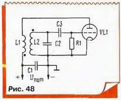
Oscillations from circuit L2C2 are fed to the tube grid VL1. Its anode current, changing in time with the oscillations in the circuit, flows through the coil and, and the energy of the amplified oscillations fed back into the circuit. For correct phasing both coils should be included as shown in the figure (start winding, wound in one direction, indicated by dots). To regulate the feedback by changing the distance between the coils.
To stabilize the amplitude of oscillation is gridlock chain C3R1 (by the way, in the first generator Meissner it was not yet). It operates as follows: during positive half-periods of oscillations on the grid of the electrons are attracted to it also charges right on the circuit plate of the capacitor C3 is negative voltage. It shifts the operating point on the plot characteristics with less steepness (lamp little closes), and the gain decreases. Resistor "grid leak" R1 allows the accumulated charge to flow to the cathode, otherwise the lamp would be closed exactly.
The capacitor C1 serves as a circuit for high frequency currents to a common wire ("earth") - it does not need to flow through the power source creating crosstalk and interference to other elements of the device, which used generator.
In the future, the American firm "Western electric" were developed more than simple and perfect generators - inductive type-Hartley (1915) and capacitive type of Kapitza (1918). We have quoted the names inventors, because their generators virtually unchanged for more than than three quarters of a century, and is still in the technical literature there are the name "scheme Meissner" or "scheme of Kapitza" without explaining what it is. Element base however has changed considerably, and as an example consider a generator made according to the scheme of inductive treatacne (Hartley) modern field transis Torah with insulated gate (Fig. 49).
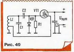
The principle of operation of such a transistor is much like trachelectomy the radio tube is the triode, but the current in it is not done in a vacuum, but in thicker semiconductor, where technologically created conductive channel between the drain (upper circuit output) and the source (bottom outlet). The conductivity of the channel is controlled the voltage across the gate - electrode, located very close to the channel, but isolated from him. When applying to the gate a negative voltage to its field as if "pinched" the channel and the drain current decreases. If filed and increasing positive voltage, the conductivity of the channel increases and the drain current increases. In any case, the current shutter missing, and it is made to complement gridlock C2R1 - chain stabilization of the amplitude of the diodes VD1, the detecting coming to the gate of the vibrations and creates a negative bias in increase of their amplitude.
Fluctuations in the penstock served with contour L1С1, which determines the oscillator frequency. The advantage of the FET is that its input impedance at the radio frequency is very high, and it is largely bypasses the circuit without making additional losses. Feedback is created by connecting the source transistor to a part of the turns of the coil L1 (usually from 1/3 to 1/10 of the total number of turns).
Generator works as follows: in the positive half-wave oscillations on top the schema of the output circuit increases the current of the transistor, which "throws" in the contour of another portion of energy.
In fact, the transistor in this generator is on a source side, and phase fluctuations at the source coincides with the phase of the oscillation at the gate, and provides a balance between the phases. The transmission coefficient of the voltage follower less units, however, the coil in relation to the source is included as a multiplying the autotransformer. As a result, total gain of the loop return communications becomes greater than unity, providing amplitude balance.
As another example, consider a generator made according to the scheme of capacitive "treatacne" bipolar transistor (Fig. 50). The actual generator assembled on the transistor VT1. His mode DC is set by the divider in the base circuit R1R2 and the resistance of the emitter resistor R3 (we have already considered such schemes in the section on amplifiers). Oscillatory circuit of the oscillator consists inductor L1 and a chain of three series capacitors C1-C3. The allotments resulting from the capacitive divider is not connected only the emitter and base of the transistor. This is dictated by the desire to reduce shunting transistor circuit because the input impedance of a bipolar transistor is relatively small.
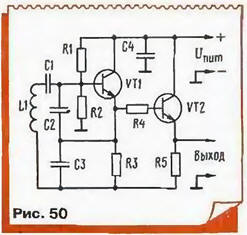
Almost the capacitance of the capacitors C2 and C3, shunt transistor transitions, try to choose a little more, and the capacitance C1 is the minimum necessary to the occurrence of oscillations. This improves the frequency stability. The rest of the work the generator is the same. like the previous.
Cascade transistor VT2, the so - called buffer amp - reducing the influence of the subsequent stages in the generator. The transistor included the emitter follower and receives the offset directly from the emitter the generator of the transistor VT1. Additionally, the relationship weakened resistor R4. All the measures taken make it possible to bring a relative frequency instability described generator to such a small value, as of 0.001 %, while in normal LC-generators it is much worse.
In radio and television receivers use a simpler generators under the scheme of capacitive treatacne, the typical pattern of one of them it is shown in Fig. 51.
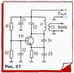
Here the contour L1C3 included in the collector circuit of the transistor, base on high frequency is connected to GND via a capacitor C2, and feedback is supplied to the emitter through a capacitive divider SS. The inclusion transistor in the common-base circuit allows to obtain a particularly high frequency generation, close to the limit for this type of transistor. The signal generator removed from the coil L2 connection.
Author: V. Polyakov, Moscow