


")

The hams are popular simple design of receivers designed for reception of local radio stations, operating in the bands long and medium waves. Original design such radio invited the Japanese radio Amateurs of Kazuhiro Sunamura (JF10ZL). Brief information about this receiver posted on his home page on the Internet at <http://www.intio.or.jp/jf10zl>. Please note: the digit 0 instead of the letter About in his e-mail address is not a typo! It The URL looks like this.
The design used a well-known idea of building receivers with low The inverter, which allows to solve the problem of filtering the signal with a simple RC-filters. The frequency of the local oscillator also define the RC-elements, and the input the oscillating circuit is non-existent. To receive close one or two radio stations broadcasting such a decision in most cases will be acceptable.
Schematic diagram of the receiver (without amplifier audio frequency) is shown in figure.
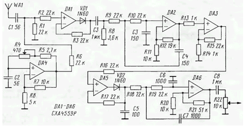
Signal with a short wire antenna WA1 comes to mixing cascade, performed at the operational amplifier DA1 and the diode VD1. He is a so-called "precision diode" (see Shyla V. L. "Linear integral chip". - M: Radio and communication, 1979. - Approx. ed.). Introduction semiconductor diode in the feedback circuit of the operational amplifier allows implement a node with an almost ideal for the detection or conversion of the signal volt-ampere characteristic.
Input impedance "precision diode" is relatively high, which provides good efficiency of the input circuit. The signal from the antenna enters the the non-inverting input of op-amp. Here moves and the voltage of the local oscillator. It made in DA4 and generates rectangular pulses, the repetition frequency of which you can change a variable resistor R4 in the range from 590 to 720 kHz. When chosen by the author of the value of the intermediate frequency of 40 kHz that provides reception in the band from 550 to 680 kHz. At higher frequencies when used operational amplifiers the reception quality is noticeably deteriorated.
The following cascade a low pass filter on OU DA2 with a cutoff frequency of about 40 kHz, and at the OS DA3 assembled the if amplifier.
The AM detection signal is implementing another "precision diode" at the shelter and DA5 the diode VD2, the signal passes through the LPF at the shelter DA6 that produce sound frequency. Variable resistor R22 is the volume control.
Feed the receiver from bipolar-source voltages of +7 and -7 V.
The repetition of the receiver should be borne in mind that relatively high performance is only required from operational amplifiers DA1 and DA4. Diodes VD1 and VD2 - germanium (this is important) small-signal.
Antenna pigtail length of about 1 m From the antenna, the author confidently took two local radio stations. This is not surprising, because the total the gain in the tract was about 80 dB.
Author: Kazuhiro Sunamura