In Amateur practice there is often a need for highly stable oscillator of fixed frequency. This generator is necessary, for example, for a shortwave receiver or transceiver. The traditional solution to this problem is to use the generator with quartz stabilization of frequency is not always enough ham, primarily because of the difficulties of the acquisition of the quartz resonator at the desired frequency. Now, when the number of Amateur LW bands reached nine, economically justified the use of local oscillators with phase locked loop containing only one quartz resonator.
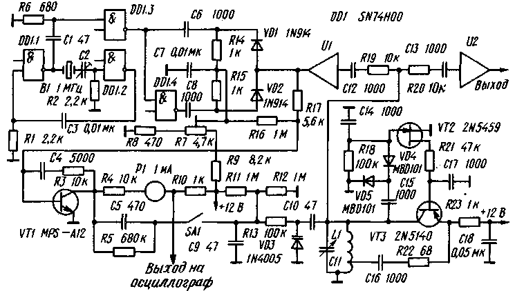
Practical diagram of one variant of this oscillator is shown in the figure. It generates a grid of frequencies in the range 1...30 MHz, a multiple of the frequency of the reference quartz resonator. In practice, this grid may have a step of 0.2 MHz to several megahertz.

Reference generator with quartz stabilization of frequency is assembled on the elements DD1.1 and OD1.2. The exact value of the frequency set trimmer capacitor C2 with the limits of capacity 5 to 50 pF. The output signal of the generator (in the form he is close to a square wave) differentiate chain R6C1, and the resulting short pulses through the inverter DD1.3 and DD1.4 receives the pulse phase detector diodes VD1 and VD2. Here moves and the high frequency signal of the voltage controlled oscillator (he performed on the transistors VT2 and VT3). Field-effect transistor VT2 is involved in the system to automatically adjust the output level of the generator is rectified by diodes VD4 and VD5 RF voltage is supplied to the gate VT2, which controls the bias current of the transistor VT3 (actually a generator). This system automatically adjusts very effective - when you rebuild a generator within the entire LW range output amplitude does not vary by more than 1 DB.
High-frequency voltage from the oscillating circuit of the generator through two broadband decoupling of the amplifier U1 and U2 respectively supplied to the phase detector and the mixer of the receiver or transmitter. Amplifier U1 should ensure very good separation between the phase detector and the amplifier input U2, otherwise the spectrum of the output signal will appear noticeable with other components (except main) frequencies that are multiples of the frequency of a quartz resonator. The error signal of the phase detector is amplified by the integrating amplifier transistor VT1 (the cutoff frequency is about 2 kHz) and fed to the varicap VD3.
The choice of the working frequency of the voltage controlled oscillator is carried out by switching the coils of the resonant circuit (L1) and tunable variable capacitor 11.
The establishment of the GPA begin with installation of a trimming resistor R7, the voltage at the collector of transistor VT1 about 6 In (a collector current of about 0.5 mA). The contacts of the switch SA1 in this case must be opened. Connected to the resistor R10 oscilloscope, rebuild the GPA variable capacitor 11. With near frequencies that are multiples of the frequency of the reference quartz resonator, on the oscilloscope screen must be observed beat signal amplitude reaches 5 V. Setting the frequency of the GPA so that the beats were close to zero, close the contacts of switch SA1, including the PLL.
In practical work with the appropriate local oscillator signal with a resistor R10 to be served at the restructuring of the local oscillator (before the loop circuit PLL) to the audio frequency amplifier to indicate the optimal adjustment of the corresponding harmonic of the quartz resonator B1 "by ear" (zero-beat).
Chip SN74H00 can be replaced by LS, transistor 2N5459 - on transistors series CP, transistor 2N5140 - GT or any other of the microwave transistor structure p-n-p (silicon or germanium), diodes MBD101 - CD, diodes 1N914 - KD521 and the like. Analog transistor MPS-A12 in the USSR no longer available, but you can replace the composite transistor comprises two transistors type CT or KT3102 static current transfer ratio of not less than 200. As decoupling amplifiers U1 and U2 used chip MSR designed to amplify signals in the tract the if television receivers. The analogue of this chip in the USSR no longer available.
Literature
Publication: N. Bolshakov, rf.atnn.ru


