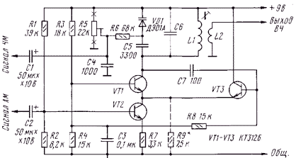
Diagram of a simple generator, which can be carried as amplitude, so and frequency modulation of the RF signal shown in the figure. Frequency modulation is the LC-circuit with varicap - VD1, C5, C6, L1 and the amplitude linear current control and VT2, respectively, of transistors VT1 and VT3 generator. Transistor VТ2 operates as an amplitude modulator. Device the introduction of FM is simplified under the assumption that the engine of the resistor R5 is not will be installed in the end position. If during the operation of such a case possible, to the points marked on the diagram by crosses, to include the limiting resistors resistance 1.5...2 ohms.

In the case when in the generator mode FM is not needed, eliminate the elements C1, C4, C5, R5, R6 VD1. If there is no need in AM mode, we exclude R1, R2, R7, C2, VT2, and the emitters of the transistors VT1 and VT3 are putting together, connecting through resistor R9 to a common wire.
In the generator you can use any high-frequency transistors p-n-p or n-p-n patterns by selecting the appropriate polarity supply voltage, and the polarity of the capacitors C1, C2 and the varicap VD1. For example, in the generator work well silicon transistors series CT, KT315, KT361, germanium - GT, P, P401 and similar settings. Resistors - MLT-0,125, and R5 is any small trimpot. The varicap - series D or similar (in depending on the frequency range), you can use a series Zener D. Polar capacitors C1 and C2 - C50-12, K50-35 or other oxide on the voltage 12 and above, the rest is ceramic.
The parameters of the capacitor C6 and inductor L1 will depend on the frequency of operation generator. For example, when the capacitance C6 750 pF, and the inductor L1, wound on a ferrite rod with a length of 30 mm, a diameter of 8 mm and containing 65 turns of wire PEL-1 0.1 mm, the oscillator frequency is approximately 430 500... kHz. Coil L2 (6 turns of the same wire) is wound next to L1.
Author: D. Ataev, Sterlitamak, Bashkortostan


