The described generator provides a wide range of harmonics of the signal stretching up to 500 MHz with a resolution of 100 kHz, 1 or 10 MHz. It can apply for calibration of scales and measurement sensitivity radio receiver devices and also be used in conjunction with a sweep generator for the formation of tags.
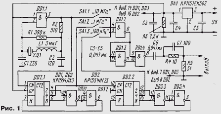
Diagram of the device shown in Fig. 1. On the logic element DD1.1 collected the master oscillator at a frequency of 10 MHz, stable quartz resonator ZQ1. His scheme is fairly traditional generators on the CMOS chips, however, it in series with the resonator installed the choke L1. Without it the generated frequency in such a switching circuit is higher than nominal.

To the output of the generator connected two decadal frequency divider circuits DD2 and DD3. In the series KR1554 have counters CRIE with the required ratio conversion, but the author to purchase them failed, so the dividers are assembled on binary counters that are part of the chip CREE. Elements of the chip DD3 provide reset counters when they reach state 10 and the appropriate conversion factor. The selection of inputs, counters and outputs for the withdrawal of a signal caused mainly by the ease of PCB layout.
The element DD1.2 - a buffer. With its output pulses with a frequency that is selected switch SA1 (100 kHz, 1 or 10 MHz), arrives at the shaper, performed on the elements DD1.3 and DD1.4. The element DD1.3 inverts the pulses from a delay of about 3 NS. Therefore, when the positive differential output element DD1.2 at the inputs of the element DD1.4 on the delay time is set high logic level, the pulse shaping logic low level of the same duration. Such pulses have a wide frequency spectrum with a resolution of, determined by the frequency of their repetition, which, as indicated above, may make 10, 1 MHz or 100 kHz.
Capacitor C6 is used for removing the DC component in the output signal, and the elements C7 and R4 exacerbate several pulses and align their range.
The voltage generator 8...12 V, and the voltage supplied to the chip, 5 In that it is stabilized by the stabilizer DA1. The output impedance of the generator somewhat less than 50 Ohms for the shunt resistor R5 output resistance element DD1.4. If there is a need in the output impedance of 50 Ohms, to increase the resistance of the resistors R4 and R5 to about 75 Ohms, it is necessary to control the output impedance of known methods.
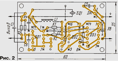
The generator is assembled on a circuit Board made of fiberglass with a thickness of 1.5 mm (Fig. 2). On the plant side of the foil elements are stored and divided into two parts dashed lines. The lower part acts as a common wire, the upper - bus power. Openings except those marked in Fig. 2 crosses that mark pike to foil common wire on the side of the setting elements for razzenkovannoe prevent possible contact with the findings of the details. Quartz resonator in glass body mounted on a circuit Board with a wire bracket that is soldered into the holes Board. To connect to the battery or power supply and what you have! output cable in PCB soldered the pins with a diameter of 1 mm from the connector RM.

Chip CRL unique enough to use in this driver device - it can be replaced with equivalent only to other members of this series, performing the functions AND-NOT or OR-NOT (in the latter case, unused the input of the element DD1.1 should be connected to GND), or on your import analog - AS. You can try to replace it CRL or CRL, but the results of such a replacement is not obvious. Chip CREE without processing PCB interchangeable on CIE or CRIE, in this case, in place DD3 you should put CLA or CRL. The place DD2 and DD3 is quite suitable one chip CIE, or any two of the counter with a conversion factor of 10 CIE, CIE, CIE, CIE and their corresponding chip series K555, KR1533, KR531, CR.
The generator used resistors MLT-0,125; capacitors - km-5 or km-6, and C3 C4 - Leadless K10-17B or similar. If no valid to install and km-5 km or 6 that is fixed, as far as possible, their findings are. The switch SA1 - WDM-2, the inductor L1 - DM-1,2.
If the generator all the CMOS chip, it is possible to apply the stabilizer 6 IN - CREN, with KREN any index and series 7806, 78M06 or 78L06. If the generator is embedded in the device with a suitable supply voltage, the chip DА1 not set definitely.
Configuring the device is reduced to setting the frequency of the master oscillator selection the capacitance of the capacitors C1 and C2 and, if necessary, the inductance of the inductor L1. To control the frequency meter should be connected to the exit of the element DD1.2, to the input capacitance and resistance of the device have not changed the load of the generator. The frequency stability of the generator labels is actually determined by the stability quartz resonator within the range of the operating temperature of the device.
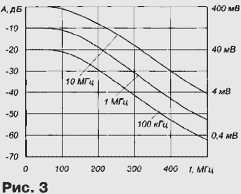
Spectrum of the output signal of the generator is very wide. In Fig. 3 shows the dependence of the level of spectral components from the frequency at the appropriate the discreteness of the marks set by the switch SA1.

Up to a frequency of 100 MHz the uniformity of the amplitude of no more than 3 dB, which allows, adding a generator attenuator, apply it to measure the sensitivity of radio receivers devices with sufficient accuracy. For higher frequencies, the decay amplitude marks is about 10...12 dB at 100 MHz.
Author: S. Biryukov, Moscow


