The most important part, the "heart" of receiving and transmitting equipment is the generator of a smooth range (GPA). Radios, transceivers, having a fixed first intermediate frequency, the GPA must produce different frequencies according to the selected range.
From the quality of its work depends on the quality of the whole device. The output signal of the GPA must be stable when the temperature changes, humidity, pressure, voltage source, etc.
The negative impact of these factors to a minimum can reduce the skillful construction of the GPA.
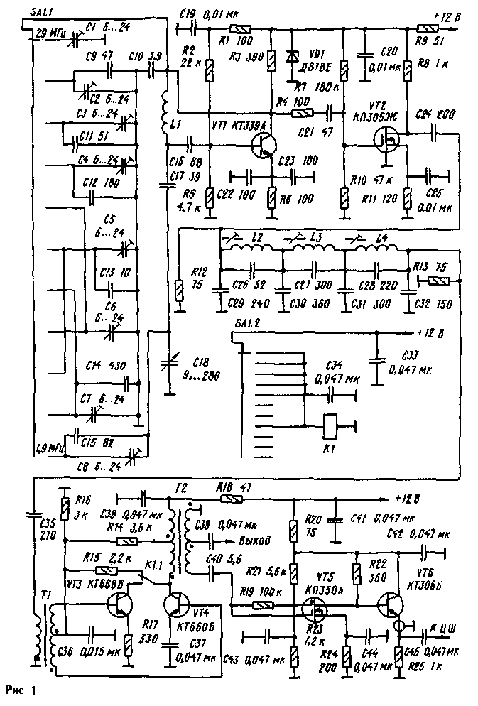
In Fig.1 shows a schematic diagram of the GPA, designed for use in receiving and transmitting equipment of fixed first intermediate frequency of 5.5 MHz. It has a small number of switching circuits, has a high stability of parameters of the output signal, its high spectral purity and uniform amplitude ranges. The number of trimming elements compared to the number of ranges is minimized.

Effective output voltage of the generator is equal to four volts at a load of 75 Ohm and has the shape of a sine wave. The generator performed on the transistor VT1 scheme Waqar. Parametric voltage regulator VD1, R9 and the decoupling From 19, R1, C20 prevent the leakage of high-frequency voltage in the power supply circuit and provide increased stability of output signal parameters in the presence of small fluctuations in voltage that occur when the transition processes (transition from reception to transmission and Vice versa).
Resistor R4 improves isolation between the generator and the subsequent cascade. On the VT2 transistor is made of a broadband radio frequency amplifier. Small internal capacitance and high input resistance of the cascade leads to a good decoupling of the generator from other cascades. The amplifier output is loaded on GPA elliptic lowpass filter of the seventh order. The bandwidth of the filter is equal to 7.33...12,6 MHz, the cutoff frequency for the filter is 12,65 MHz. For all spurious products is ensured by the suppression of more than 35 dB. Input and output impedance of the filter is about 500m.
The filter output is connected to the input of the cascade, transistors VT3 and VT4, which is a switchable amplifier-doubler. On the ranges of 1.9 MHz, 3.5 MHz, 7 MHz, 14mgts, 18 MHz, it operates as an amplifier, and ranges 10 MHz 21 MHz 24 MHz 28 MHz as a doubler. During transition from double mode boosted manifold transistors is disabled and the transistor VT4 is translated into a linear mode of amplification (class A) flow in the base circuit of the additional positive bias due to the connection of the resistor R15. In the double mode the signal from the input transformer T1 is fed in antiphase to the bases of both transistors. The collectors of transistors when connected in parallel and loaded onto the input winding of the transformer T2.
The output signal of the GPA is removed from the middle of the output winding of the transformer, and cable isolation amplifier with a digital scale connected to complete the winding. Last transistors VT5 (amplifier) and VT6 (emitter follower). Resistor R25 is set directly on the digital scale. The emitter of the transistor VT6 is connected to the input digital scale piece of the coaxial cable RK-75. This amplifier, having a good buffer properties, has a gain of about 10 in the frequency band 100 kHz-50 MHz. Switching amplifier-doubler (VT3.VT4) mode of amplification in the double mode is made by the node to the relay K1, the disk switch SA1.2 and the capacitors C, C34.
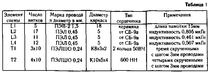
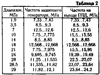
Winding these coils and transformers are given in table. 1, and the frequency produced by the generator in table.2.


Transistors can be replaced by CTB or similar. Transistors CTB - CTB, CTB; KPA - KB, KB; CTB - CTB. Trimmer capacitors C1-C8 air-dielectric type KVM. Relay K1 type RAS (passport RS4.569.424) or RAS (passport RS4.569.438). Switch type PG, PGG 11 regulations and 2 directions.
Tuning begins with laying the 7 MHz selection of capacitor C13 and C5 tuning. After packing produce temperature compensation by replacing the capacitors With 10, C13, C17, C22, C23 capacitors are equal in value but different TKE.
Laying the remaining ranges produce the selection of capacitors C9, C11, C12, C14, C15 and tunable capacitors C1, C2, NW, C4, C6, C8, and then temperature compensation is replacing the capacitors C9, Cll, C12, C14, C15 according to the method described above.
When laying range 29 MHz may require the installation of additional capacitor 20...30 pF parallel capacitor C1.
Then set the cascade transistor VT2 picking up resistor R8 to the maximum of the signal at the drain of this transistor. To do this, temporarily replace the resistor R8 and variable resistor km, setting up a cascade, and then by measuring the resistance of a resistor, replace it with regular - close at face value.
Rotation of trimmers coils L2,L3,L4 produce setting the low-pass filter with the purpose of obtaining uniform characteristics in the frequency band of 7.33...of 12.6 MHz and the cutoff frequency 12,65 MHz. The control lead of the oscilloscope or meter response.
Tuning the amplifier-doubler (VT3.VT4) start in the double mode in the range of 10 MHz selection resistor R14 to obtain at the output (C39) the maximum amplitude of the signal and the correct form of the sine wave.
Then, by switching the generator on the 14 MHz band, in which the cascade works in 'boost mode, select a resistor R15 to obtain the maximum signal output and the correct form of the sine wave.
Cascade transistor VT5 set to the maximum output (s) the selection of the resistor R22.
If generator output is observed irregularity in amplitude of the output signal in different parts of the frequencies, you have to take the resistors R12, R13 high impedance until one of the shortfall. Then in response the generator will appear uneven in the form of humps and dips. Rotation of trimmers coils L2, L3, L4 must be offset humps characteristics in those areas where previously, there had been signals output frequencies with small amplitude and failures. Selecting resistors R12,R13 adjust the height of the humps and the depth of the dips in the frequency response.
To reduce the output voltage of the GPA by selecting a resistor R4.
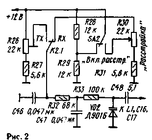
For the introduction of detuning you can use the scheme shown in Fig.2. Positional notation elements continue in Fig. 1.

Fig.2
Trimmer resistor R26 is used to set the frequency of the GPA in the transmit mode is the same as when receiving. Include a detuning switch SA2. A variable resistor R30 control the frequency change. The magnitude of the tuning range depends on value of capacitor C48. It is greater, the greater the capacity of this capacitor.
Author: Vladimir Rubtsov (UN7BV) Astana; Publication: N. Bolshakov, rf.atnn.ru


