The author of this article conducted experimental work to study characteristics of different generators on the chip of the CMOS structure. As a result he selected some of the most interesting, in his view, their options execution, which we present to our readers.
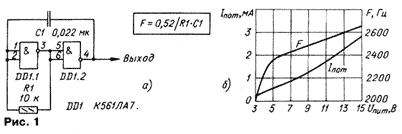
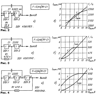
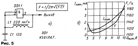
This article briefly describes several circuit design generator rectangular pulses derived from different chip series C. On its structure article is a comparative reference. To each diagram lists parameters and characteristics (see table) and graphical dependencies the supply current and the generated frequency of the supply voltage.
The generator according to the scheme in Fig. The lower limit of the resistance of the resistor R1,com The greatest generation frequency,MHz The minimum voltage,V The change in frequency when heated to 85°C, % The duty cycle of the output pulses 1,and 1 2 2 -4 2 2,and 1 2 4 - 2 3,and 0,56 2 2,5 -5 >2 4,and 0,56 2 2 +2,5 <2 5,and - 1,3 3 - <2 6,and 1 1 1,4 -11 >2In addition, for each generator is specified formula, which calculates the the value of the generated frequency depending on the component values castorocauda circuit (frequency - in Hertz, resistance in ohms, capacitance in Farad, the inductance in Henry; more conveniently, by the way, for RC-generators: frequency is measured in kilohertz, resistance in kiloomah, the capacitance in the microfarad; LC-oscillators: frequency in MHz, capacity - almost never, inductance in millihenry). The calculation formulas for the number of generators obtained empirically.
All of the presented characteristics of the generators obtained as a result of experiments with specific samples of chips. With other instances of the chip characteristics can be some great. Formula to calculate the frequencies correspond to the 5 V supply voltage and temperature the environment of 25°C. the Load capacity of the generators is the same as in elements chip series C. The upper limit of voltage generators also defined the applicable series of chips and is equal to 15 V, as shown in the lower table. The upper limit of resistance of the resistors I installed from practical considerations at the level of 40 MW.
In generators with positive capacitive feedback the amplitude of the pulses at the input element may exceed the supply voltage. In these cases input protection diodes and current begins to flow. To limit this current in the input circuit have to install the resistor 1...150 ohms, as specified in [1] and used in [2].
Everything covered in this article, the generators have a mild arousal. Otherwise words, no matter how slow increase in the voltage, the generator still work.
The generator on the elements 2I-NOT (Fig.1,a) was already known for classic and a large number of publications. He keeps working priyangani supply voltage u pit up to 2 In, with, however, is significantly reduced the frequency of oscillation.

The duty cycle is close to two at any supply voltage. As a result heating of the housing of the chip frequency decreases slightly (by 4 % when 85°C).
Such a generator may be made of two logical elements of the 2 or NOT (Fig.2,a), two inverters (Fig. 3,a), and three inverters (Fig.4,a). The details and differences on two generators and three inverters can learn from [3]. Note that the generator on the elements 2OR-NOT frequency generation almost independent of the case temperature of the chip, and generators the frequency inverters are very stable on a plot of u n and m=9...15 V.

In Fig.5,and shows a diagram of a simple LC-oscillator with a logical element 2I-NOT. LC circuit shifts the phase of the output element 180 deg., in this results in the excitation of the generator. Such generators are well operate at higher frequencies, mildly excited and differ high temperature stability [3].

With increasing frequency in excess of 1.3 MHz, the amplitude of the output pulses begins to fall.
The generator can also work elements 2 OR NOT, and in this case he generates rectangular pulses, and oscillations, in the form similar to sinusoidal.
For stable operation of the generator impedance of the LC circuit should not to be less than 2 ohms. The oscillation frequency coincides with a resonant frequency LC-circuit. The dignity of the generator - high temperature stability frequency.
Similar in structure generators can be performed on one element of the trigger Schmitt (Fig. 6,a). When the supply voltage is close to maximum, they are very frequency stable. In addition, they are extremely economical at a voltage power In less than 6 consume a current of only a few tens of microamperes.

Literature
Author: C. Alimov, Cheboksary


