The tone pulses can be used to test the dynamic parameters gauges and autoregulation level, as well as noise reduction devices. Stand with the tone generator pulses will be useful in the study of amplifier and the acoustic equipment.
The linearity and accuracy of the meter level it is easy to check using a conventional sound signal, but for check their dynamic parameters, you need a tone generator pulses (GTI). Such generators offered by Amateur radio operators, often do not match norms of where to check the level meters (Yiwu) frequency sine wave the pulses accepted 5 kHz, and the beginning and end of the pulses coincide with transitions signal through zero.
Similar problems arise when configuring autoregulation sound level signals. The recovery time is 0,3...2 easy to see on the oscilloscope screen, but time limiter (limiter) or the compressor may be less than 1 MS. For measurements and observations of transients in audio equipment conveniently to use the GTI. In this case, the frequency of filling pulses preferably modify, using a tunable external generator. For example, at a frequency fill 10 kHz duration equal to one period of 0.1 MS, and observed the process of triggering the definition of response time is not complexity. Sound pulses from the output of the GTI should have a level difference of 10 dB.
In foreign literature are usually offered to measure time tripping with a sudden increase in signal level 6 dB above normalized values, but real signals have a substantially larger difference levels. By applying this methodology, often explains the "clicking" import autoregulation level. In addition, almost any sound generator can abruptly change the level by 10 dB, the use of such a level difference is convenient for observation. Therefore, in domestic practice it is customary to measure dynamic parameters of autoregulation when you change levels by 10 dB.
Unfortunately, the switches of the signal level of many generators in the moment switch give a momentary power surges, and to measure time positives make use of them fails, because avtoregulyator "shut up". In this case, the GTI can be very helpful.
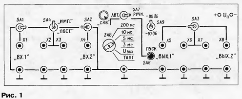
The majority of Amateur radio operators to conduct such measurements have often, and such a device appropriate to include in the measurement of the stand with more features. On the front of the patch posted items, very handy for connecting measuring instruments and custom equipment. In Fig. 1 shows the approximate location of connectors (or terminals sockets and switches.

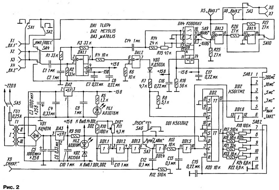
On the scheme (Fig. 2) shows these switching chain.

(click to enlarge)
Input Jack X1 ("BX.1") and x2 ("BX.2") are intended for connection of inputs custom equipment. The switches SA1 and SA2 allow you to connect the inputs to the connectors x2 and X3 or connecting them to a common wire when measuring the level of integrated interference. In comparison with the toggle buttons give more visual the idea of connecting the inputs. In the Central socket x2 and X3 are connected the audio frequency generator and voltmeter to monitor the input voltage. The connectors X5 and X8 are for connecting outputs configurable equipment. One of the outputs can be activated by a toggle switch SA3 to the connectors X6 and X7 for measuring instruments. When setting up sound equipment comfortably use a distortion meter and oscilloscope.
For switching circuits do not need any power sources, such switching is very convenient to test different equipment.
If the dual switch SA4 (Fig. 1) is at "POST", the signal from a constant level is applied to x2, XS, behaves, depending on the situation toggle switches SA1 or SA2, connectors X1, X4 to the inputs of the tested equipment. If we translate SA4 in the upper position, the signal from the generator goes to the inputs 1 and 2 through the circuit of the GTI. In this case, the stand must be connected to AC current is 220 V.
Toggle power-SA5 located on the rear panel and the front display LEDs HL1, HL2 (display "+" and "-"), indicating the presence of the bipolar voltage ±15 V.
For the formation of tonal pulses using an electronic switch DA4. Of the pins 16 and 4 the value of the voltage signal changes from the normalized value to zero, and the pins 6, 9 level difference when creating a set a variable resistor R15. The mode selector produces a toggle switch SA9.
Tone fill the pulses coming from the generator to e switch through the buffer opamps DA1.1. Second OU DA1.2 is used as comparator, generating a synchronization signal the beginning of the pulse when the signal fill through "zero". The pulses from the comparator are served to the clock input D-flip-flop DD2. On the D input (pin 9) comes a pulse from single-shot collected on the second trigger DD2.
The pulse width is changed with the switch SA8.2 of changing resistance in the charging circuit 15 connected to the input R (pin 4) the single vibrator. To set the pulse duration it is quite usual oscilloscope. A single-shot is triggered by signals from the generator rectangular pulses on the inverter DD1.1 - DD1.3, or in the manual mode button SA6 "START". If the toggle switch SA7 in position "AUTO", the duty cycle (the period) pulses is adjusted with the variable resistor R11 "СSW.".
It is very difficult to observe transients on the oscilloscope screen when the duration of the tone pulse of 3 MS and a large duty cycle. The task is simplified for oscilloscopes with external trigger while waiting for the scan. For them synchronization on the back of the booth displayed the nest X9 "SYNC.". Launching the pulse is fed to an electronic key with some delay relative to timing determined by the choice of parameters R13, C13.
The high level at which the electronic switch DA4 skips tone the signal appears with a positive differential voltage from the comparator after the appearance of the pulse from single-shot and ends after the end of this momentum (the next difference signal from the comparator). This achieves the coincidence of the beginning of the tone pulse with a signal transition via fill "zero" and satisfied the requirement of generating an integral number of periods. When the position of the switch SA8 "UВых" the voltage at the control input equal DA4 zero and you can set the output voltage of the generator corresponding to nominal input level. In switch SA8 "the BEAT." chip DA4 is controlled by the voltage coming directly from the clock generator. The switching frequency set by the variable resistor R11.
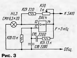
After the electronic switch via a repeater DA1.3 and the switches SA1 and SA2 the tone pulses are received at the inputs configurable hardware. In the device there is an inverter DA1.4 and the switch SA10, which can be used for out-of-phase signal on one input relative to another. Such an inverter for instance, when checking the correlation of signals in stereo systems, in AC, but perhaps it is more useful to collect the OS built-in generator the tone in the circuit shown in Fig. 3. In this generator easy get Kg less than 0.2% and many tests to avoid the use of external stand generator.

To check the level meters need to connect the inputs of two channels (for a measure of the stereo signal) to the corresponding input connectors. Then in the "UBыx" switch SA8 to set the generator output normalized the value of the signal level with F = 5 kHz and monitor the readings of both channels meter. For example, in the level meter [1] the LEDs corresponding to the value "O dB" must light up simultaneously, and the error of the scale here exceed 0.3 dB. Toggle SA9 set to "80dB". Then take turns after switch SA8 in the "10 MS", "5ms" and "3 MS" and check the compliance of the testimony of the correctional institution. The position of "200 MS" SA8 use when checking gauges mean values of level, which, unfortunately, predominate in household equipment.
In order to monitor precisely the amount of time of return, a variable resistor R11 ("СSW.") set the signal frequency of the generator of rectangular pulses, in which immediately after extinguishing the led, corresponding to a value of -20 dB at the scale of Yiwu, should the next pulse. To then determine the period of the signals with an oscilloscope is easy. The extinction of the LEDs on both channels occur synchronously.
When testing the dynamic parameters of autoregulation signal level used position "-10 dB" switch SA9. The inputs and outputs connected to all connectors. The outputs of the control channels alternately, though a two-channel oscilloscope, nothing prevents to control both simultaneously output. The output of the generator of sound frequency at the position "UBыx" switch SA8 put the signal level 10 dB higher than the normalized value. Then translate SA8 on the pulse of any duration, and the switch SA7 - in position "The MANUAL.". The key remains off and allows you to control the voltage on the connectors X1 and x2, which should correspond to the normalized value. Then switch SA7 translate the GTI in the automatic mode, and selecting a the desired pulse duration and duty cycle, see transients on the output of the avtoregulyator. If the oscilloscope is running in standby mode running from sync pulses, it is easy to determine the response time and the presence of noise tripping or overshoot.
In the GTI used four chips, and the current consumption is very small. It allows is integrated stabilizers provide a simple parametric voltage stabilizer on the Zener. On the other hand, by installing a more powerful integrated stabilizers DA2, DA3 series and da do, they can be used to power the custom device layouts, placing an extra connector on the rear panel (not shown). In the chip protects from short circuit, often when experiments.
The front panel of the stand has dimensions 195x65 mm. the body of the stand are made of steel.
To check the connection of the equipment convenient socket-terminals type LRZ. Apart from them on the panel of the stand can be set, based on a validated instrument, connectors appropriate design, for example, the nests of the "Tulip", "Jack", ONTs-SH or other.
Double toggle switch SA4 - PT-7, P2T-1-1 or similar. Switch SA2 - disk PG-8-PICK. The SA6 button "START" can be of any type non-latching, for example, KM1-1.
Chip DA2 CCN [2] can be substituted by functional purpose. As DA1, you can use a chip with four shelter types LF444, TL084, TL074 [3] or COD.
The Board mounting device - a printed or mounted on the breadboard.
Stand with the GTI you can use when testing companding systems noise reduction, dynamic filters and other sound equipment.
Literature
Author: E. Kuznetsov, Moscow


