


")

In experiments with widespread CMOS chip CLA author managed to implement two simple generator that we offer to the readers.
In Amateur practice is often a need in high-stable the generator, and the quartz resonator with the desired operating frequency can not be found. If there is a resonator with a higher frequency, it is possible, for example, to make generator with quartz stabilization of frequency, and then use the divider to lower it to the required size. For such a device typically requires at least two chips. Meanwhile, when there is a ham radio operator has a resonator working frequency three times higher than required, you can solve the problem much easier. In the generator, the circuit of which is shown in Fig. 1, the author used quartz the resonator for a frequency of 500 kHz, square wave generator output had a frequency of 166,(6) kHz. You can take resonators and at other frequencies (from tens kHz to several MHz), but will have to pick up experimentally capacitor C1 and resistor R1. (The higher the frequency, the nominal values must be smaller, and Vice versa).
But how does this generator, if at frequencies below the main no resonances in quartz not? But the fact is that in shown in Fig. 1 RC-oscillator there are all conditions for self-excitation. Indeed, the parallel capacitance of the quartz and cartegories forms a chain of positive feedback, and the resistor R1 closes the EP DC, which provides a linear mode the work of the first two elements DD1 chip. Selecting the resistor R1 and the capacitor C1, set the generator frequency is slightly lower than the operating frequency of the quartz the resonator is divided into three. The steep fronts of the rectangular pulses excite the resonator on the CSO main frequency. Emerging findings the voltage a frequency of 500 kHz synchronizes RC oscillator, and very hard, with accuracy to the phase.
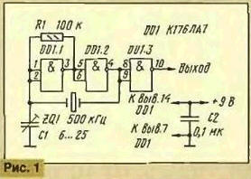
All of this can be observed with an oscilloscope by connecting the probe with low input capacity (so as not to disrupt the operation of the generator) to the right under the scheme conclusion quartz resonator. Visible on the screen, like a square wave with frequency 166,(6) kHz are superimposed smaller in amplitude sinusoidal oscillations with a frequency of 500 kHz. The band synchronization generator described is quite large, therefore, these destabilizing factors, such as changes in certain limits supply voltage, temperature and component values practically do not affect his work. The stability of its frequency is entirely determined by the used quartz resonator.
Another generator, unlike that just described, has a very wide the range of adjustment, and here about frequency stability is not an have to - it completely (the temperature dependence was not studied) is determined by the stability of the control voltage. The scheme of the generator is shown in Fig. 2. There is only one blocking capacitor, which prevents the penetration of oscillations of the oscillator in the control circuit of the frequency and protects it from external interference. In the work of the generator actually he is not involved. All elements of the chip are connected in series, the first three of them assembled the generator and on the fourth output buffer amp.
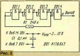
The feedback circuit formed by the resistor R1, the DC of it negative and therefore provides a linear mode of operation of the elements of the generator. In each of these signals is delayed by a certain time, and duration this delay is highly dependent on the voltage - the higher the quality, the delay less. The phase shift of the oscillations is proportional to the product of delay time frequency. At sufficiently high frequencies, the phase shift in each element of the chip 60cm, and all three add up to 180°. As a result the EP turns into positive and at this frequency the generator is excited. If you increase supply voltage 3 to 12 V, the oscillator frequency varies from about 300 kHz to 6 MHz, i.e., 20 times. Current consumption increases at the same time from a share milliamperes to 2 mA. The generator is blocked, for example, the mediumwave range (500… 1600 kHz), the voltage must change from 3.5 to 5 V. The frequency range can be changed by selection of the resistor R1.
The advantage of the described generator - exclusive simplicity, and the main the disadvantage is the strong dependence of the output voltage from the frequency.
Author: V. Polyakov, Moscow