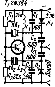
If the connected power source has a positive terminal at the top (the scheme), the contour of the collector objective L1, C1, Q1 is shunted by a diode D1 through which flows a collector current. In this case the circuit L2, C4 and quartz Q2 determine the frequency of the generator. The voltage of this frequency is removed from the divider formed by capacitors C2, C3.

If the connected power source is of the opposite polarity, the diode D2 is shunted by a circuit L2, C4, Q2 and generated frequency is determined by the parameters of the upper contour. As the active element of the transistor T1 is used germanium transistor p-n-p type. The device was applied to the coils L1, L2 inductance of 5.6 mH and quartz at frequency 455 and 458 kHz, respectively. By changing the parameters of the resonant circuits can be obtained voltage various other frequencies.
Instead of the transistor 2N364 you can use KT361. The diodes D1, D2 - DG.
Literature
Radio No. 11, 1970, c. 59.
Publication: N. Bolshakov, rf.atnn.ru


