A feature of the OS series KR is advanced to a voltage source supply the valid interval of the input and output voltage. This allows apply them in a variety of devices with low-voltage power supply, where it is important maximum use voltage source.
The circuit of the generator, which produces two output signals - triangular and rectangular shapes, is shown in Fig. 1.
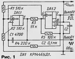
At the junction of resistors R1 and R2 formed artificial midpoint voltage which determines the mode both the OS. At the shelter DA1.1, the resistor R4 and the capacitor C1 is constructed integrator, and OH DA1.2 with the resistors R3 and R5 is a Schmitt trigger. Feature trigger - very a wide hysteresis loop the Uгист = u n and m R3/R5 and accurate and stable thresholds switch. Wide loop allows to obtain the maximum amplitude a triangular voltage at the output of the integrator, since the amplitude of this signal corresponds to the width of the loop.
The oscillation frequency is possible with sufficient accuracy for practice be calculated by the formula fr = R5/4C1·R3 - R4. When specified on the circuit component values frequency generation equal to 265 Hz, and with the change of supply voltage from 2.5 to 7 In it the deviation from the specified value did not exceed 1%.
The described device is simple to turn into a generator, voltage controlled (VCO), if the non-inverting input of op-amp DA1.1 disconnected from an artificial mid-point the power source and to apply for this input control voltage. Dependence the frequency of oscillation of the voltage control ISID illustrates the lower curve on Fig. 2. She charged at a voltage of 5 V, the capacitance of C1 capacitor 430 PF and DA1 - CRUD.
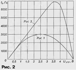
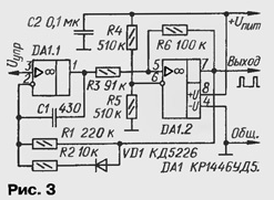
The initial portion of the curve from 5 to 500 mV has good linearity, frequency in proportion varying from 10 to 1000 Hz. If you want to increase the length of the line section, you can make the integrator asymmetric (Fig. 3). At low-level output voltage Oh DA1.2, i.e. at the output of the generator, there is a relatively slow process of integration, slew rate the voltage at the output of op-amp DA1.1 is determined by the voltage Uynp and time constant chain C1R1. Full scope of the sawtooth voltage at the output of op-amp DA1.1, as in the generator according to the scheme of Fig. 1, equal to the width of the hysteresis loop of a Schmitt trigger, collected at the shelter DA1.2, therefore, the duration of the forward stroke tnp= u n and m·R1·R3·C1 / Uynp·R6.
When the output of op-amp DA1.2 low voltage level gives way to high, opens the VD1 diode in parallel to the resistor R1 is connected to R2 and the speed integration increases significantly, and the length of the return stroke accordingly decreases. So with a high degree of accuracy can be considered, what is the period of the generated signal determines the duration of the forward stroke, and frequency equal to: fr = Uynp·R6/u pit·C1·R2·R3.
In Fig. 2 shows the experimentally obtained dependence of the frequency of the output pulse (upper curve) of the voltage control oscillator circuit Fig. 3. Plot a linear relationship was longer than six - fold to values control voltage 3 (up to the output frequency 6 kHz).
The dependence of the oscillation frequency of the voltage control near zero in a large extent depends on the zero shift of a particular instance of the used OS. On practice the frequency of the output pulses may be equal to zero as in small the plus voltage ISID, and in sub-zero.
In the practical application of the generator in cases where it may exceed the control voltage on the supply, the gap control circuit (pin 3 Oh DA1.1) should include the resistor of several tens of the shortfall.
In Fig. 4 is a diagram of the MODES in which you can fine tune the zero.
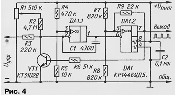
When low voltage at the output of op-amp DA1.2 (generator output) of the transistor VT1 is closed and the output voltage of the integrator at the shelter DA1.1 gradually decreases with speed, proportional to a control voltage. When it drops to the lower threshold switching of the Schmitt trigger at the shelter DA1.2, its output will appear high the level that will open the transistor VT1. As reinvestiruja input op amp DA1.1 with the divider R4R5 voltage is about 100 mV, this op amp will switch to the switch and the voltage at its output starts to rise with a velocity determine the maximum output current of the operational amplifier and the capacitance capacitor C1. When the voltage at the output of op-amp DA1.1 reaches the upper threshold switching of the Schmitt trigger at the shelter DA1.2, it will switch, the transistor VT1 is closed, the process will repeat.
As the duration of the return stroke is much less than direct, frequency depends on the control voltage is quite linear.
Without the resistors R1 and R2, the frequency is zero when the input voltage is equal to the voltage across the resistor R5. Circuit R1R2 allows you to make frequency was zero at zero control voltage.
The width of the hysteresis loop of a Schmitt trigger at the shelter DA1.2 when R7=R8 equal Uгист = U pit/(1+2R9/R8), and the generated frequency can be determined according to the formula fr= Uynp (1+2R9/R8) /u pit/·C1·C3.
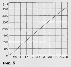
In Fig. 5 shows experimentally removed the dependence of the frequency vihotzeitani signal operational amplifier DA1.2, which is quite obespechivajut OU considered series. It is also important that the amplitude of the signal at the output of op-amp DA1.2 was less than the limiting level of the signal at the output of op-amp DA1.1.
In the prototype is achieved with a reduced supply voltage Oh DA1.2 compared to OS DA1.1 Close to the effect in the generator according to the scheme of Fig. 6 achieved by transferring the shelter DA1.2 boosted - limits, resulting in his the output oscillations are formed to be trapezoidal in shape, with low level harmonics compared with the rectangular signal generated by the OS in the relevant the prototype.
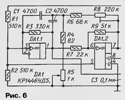
When indicated in Fig. 6 component values and supply voltage of 5 V by resistor R5 can rebuild the output frequency in the range of 1600...5800 Hz, however, at a frequency of 3000 Hz and more the shape of the generated sinusoid is noticeable distorted and the amplitude has fallen to 60% from the value at low frequency. When C1=C2=0,047 UF band adjustment is $ 170...640 Hz in good shape signal, and the uniformity of the amplitude on the strip did not exceed 10%.
Author: S. Biryukov, Moscow


