


")

Measuring the generators, in which the desired frequency is set using the keyboard, the readers of the magazine known (see, e.g., article Piskareva A. "Frequency-generator-watch" in "Radio", 2002, No. 7, pp. 31, 32). As a rule, these devices are implemented on the microcontroller, the range of generated frequencies is limited to a few megahertz, but obtaining the exact value of the frequency impossible. Described in article generator also contains a microcontroller, but used it only to control ASIC - frequency synthesizer AD9850. The use of this chip allowed us to expand the frequency range from fractions of Hz to 60 MHz, within which you can to get any value frequency of exactly 1 Hz.
The proposed generator is made based on the chip AD9850 company Analog Devices, which is a complete DDS (Direct Digital Synthesis) frequency synthesizer with built-in comparator. Such synthesizers is unique in its precision, virtually unaffected by temperature drift and ageing (the only the element that has the characteristic of analog devices instability, is digital to analog Converter). Due to the high technical characteristics DDS synthesizers in recent times, replacing the conventional analog the frequency synthesizer. Their main advantage - very high resolution frequency and phase that are managed in digital form. Digital interface makes it easy to implement a microcontroller-based control. More detailed description of the principles of direct digital frequency synthesis can to learn, for example, in [1].
Block diagram of the synthesizer AD9850 depicted in Fig, 1.
Its basis is the phase accumulator, forming the code of the instantaneous phase of the output signal. This code is converted into a digital value of a sinusoidal signal, which by means of the DAC is converted to analog and filtered. The comparator provides output signal of rectangular shape. Its frequency fout (in Hertz) is determined by the formula fout = Δfin/232, where fin - clock frequency, Hz; Δ is a 32-bit value code frequency. The maximum value of fout is not can exceed half the clock frequency.
Main technical characteristics AD9850 (5 V supply)
- The crystal oscillator, MHz......1…125
- Maximum current consumption (at fin = 125 MHz, mA......96
- The number of bits of the DAC......10
- Maximum DAC output current (Rset = 3,9 kOhm), 10,24 mA …
- The maximum integral nonlinearity of the DAC, MSP......1
- The voltage at the output of the comparator, In:
- minimum high-level 4,8 …
- maximum low level of 0.4 …
To load data into the AD9850 chip designed for parallel and serial interfaces. In the latter case, data (word length of 40 bits) enter through the entrance D7. Each bit of data is accompanied by a pulse of positive the polarity of input synchronization W_CLK. After loading the control word for the pulse of positive polarity at the input FQ_UD substitution parameters the generation of new ones. Bit assignment control word are shown in table. 1.
Schematic diagram of the generator shown in Fig. 2. Controls the synthesizer DD2 the microcontroller DD1.
It polls the keyboard SB1-SB16, displays information on the LCD indicator HG1, computes the value of the code frequency and transmits it via serial interface in synth DD2. A sound projector 1 is used to confirm button presses keyboard. Chip AD9850 (DD2) used in the standard inclusion [2]. On the output of the DAC filter is enabled Z1. After the filter the signal is sinusoidal served on a nest XW2 and to the input of the comparator chip DD2 (pin 16). Output the last square wave signal is supplied to the socket XW1. As a clock generator for DDS applied crystal oscillator G1. Trimmer resistor R7 regulate the contrast of the image on the display HG1.
After reset of the microcontroller configures the LCD indicator on HG1 mode sharing the bus 4 bits, which is necessary to reduce the number of lines I/o, required for recording information.
Run the generator with the keyboard, consisting of buttons SB1-SB16. Since all lines In port, which input is connected to a power source via resistors, the need for external resistors, "pull-up" ports RB4-RB7 on the power lines, no. The resistors R3-R6 protect the outputs of the microcontroller overload if you accidentally press multiple buttons simultaneously.
The desired frequency is set from the keyboard. To do this, pressing the relevant digits, enter the desired value (in Hertz) and press the button "*". If the frequency does not exceed the maximum allowed on the display for a short time, the message "OK" and the generator goes into operational mode, and if exceeds, - "Error". In this case it is necessary to press button "C" ("Reset") and to retype the correct value. Just do the error in the process of entering the frequency. Double clicking this button places the instrument in the operating mode set before the frequency value.
In the operating mode in the right-familiarity indicator blinks an asterisk. If the current frequency is entered from an external control unit (e.g., computer), to return to the frequency displayed on the indicator, just press the button "*".
The button "U" (Up - up) and "D" (Down - down) enable a step change the output frequency of the generator, respectively increasing or decreasing the value decimal places per unit. The desired number of decimal places chosen by moving the cursor buttons "L" (Left - left) and "R" (Right - right).
When you click "*" the frequency and the position of the cursor is stored in the nonvolatile memory of the microcontroller, thus following power is interrupted, the operation mode is automatically restored.
Since the computational power of the microcontroller is limited, the value the output frequency is set with an accuracy of about 1 Hz, which is sufficient to the majority of cases. To fully realise the possibilities of the synthesizer, can be controlled via PC. For this purpose, the generator needs to be developed an addition of a node, the diagram of which is shown in Fig. 3. PC (or other controller device) connected to the socket XS1. At a low logical level to address the inputs And the multiplexer chip DD3 connect the control inputs of the synthesizer to the microcontroller DD1, and at high - to an external device. Signals control comes via the contact "ENABLE" sockets XS1. Resistor R19 provides a low logic level on the address inputs when DD3 unconnected the device control.
The generator is assembled and tested on the breadboard. If we fail to purchase the Board under the SSOP package for the chip DD2, you can use to connect it conclusions relevant to the pads short (length of 10…15 mm) pieces of tinned wire with a diameter of 0.2 mm. Conclusions 1,2,5,10,19, 24, 26,27, 28 connect the common wire one segment of greater length.
LCD led HG1 - ITM1601 (16-character, single-line built-in controller). HA1-any piezoelectric sound emitter with built-in the generator, designed for a voltage of 5 V. as a clock generator (G1) you can use the micro-crystal oscillator frequency up to 125 MHz, the permissible use of such node with quartz stabilization and discrete elements.
The control program of the microcontroller depends on the frequency of the clock generator.
"Firmware" for the most common values
Program codes for generator with a frequency of 32 MHz is shown in table. 2.
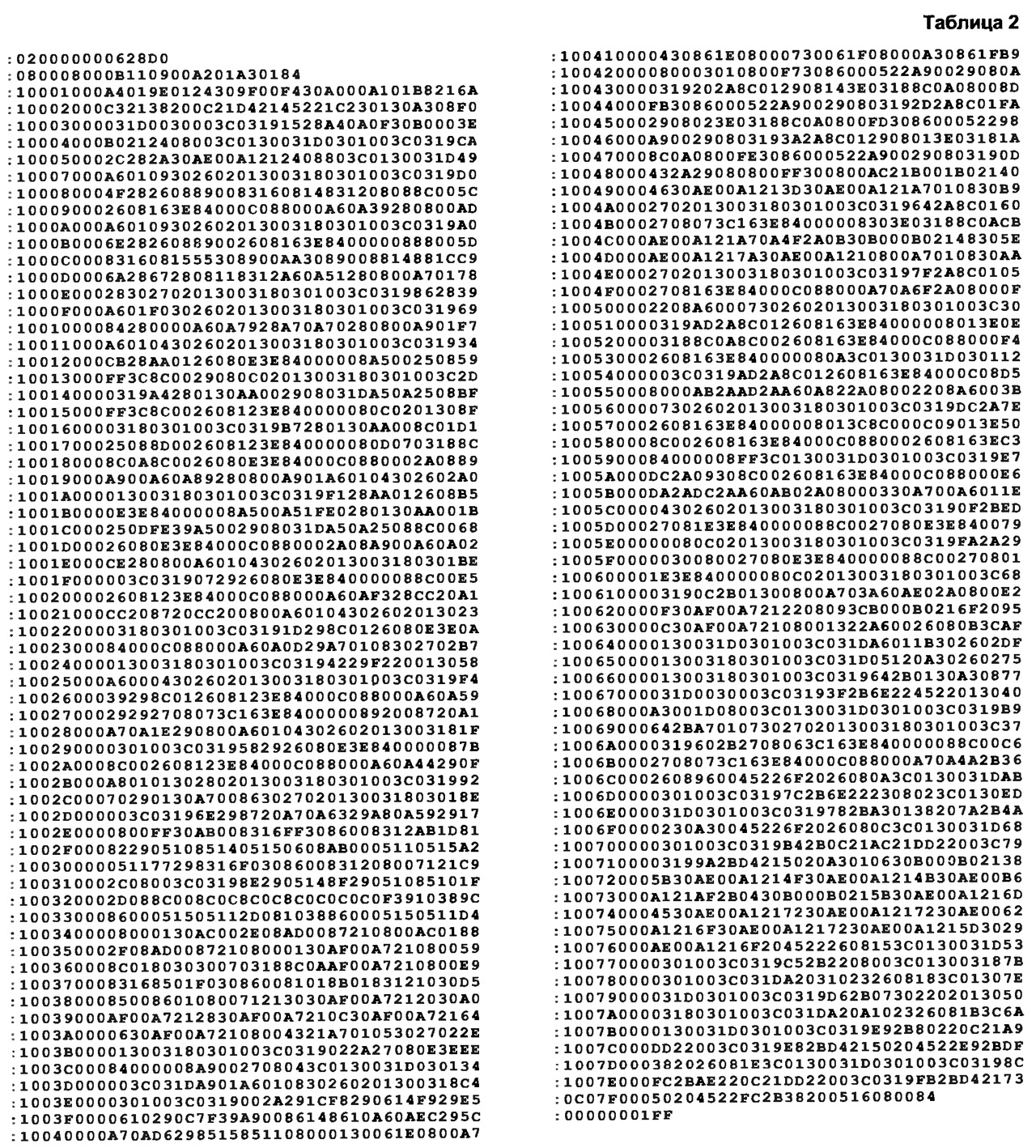
(click to enlarge)
To program the microcontroller in the configuration word set the following bit meanings: the type of oscillator (OSC) RC watchdog timer (WDT) - off delay after power on (if set) - resolved.
Literature
Author: S. Kuleshov, Kurgan