


")

Currently, many replace TV third generation more modern. Throw away your old and malfunctioning to the dump - sorry. Meanwhile individual units of these devices you can gather simple devices. About one of the unexpected examples of a selector of television channels and described in this article.
From the selector TV channels SC-M-24-2, you can collect the console to the oscilloscope, a sweep generator to view the frequency response of the radio and television equipment in a wide range of frequencies - 0,5…100 MHz. Thus manufacturing the device is primarily in the feeding Board of the channel selector excess for this device detail and the addition of a small number of new.
This sweep has a classic block diagram of the devices of this group (Fig. 1). In it has two generators G1 and G2, the tunable frequency change voltage. The limits of adjustment of the first sweep generator - 150…250 MHz, and second - 150…160 MHz. Frequency deviation of the generator G2 is achieved by changing the varicap capacitance in the resonant circuit of the sawtooth voltage from the unit oscilloscope sweep. High-frequency voltage with these generators is served on the mixer U1, the output of which oscillations are generated difference frequency 0,5…100 MHz with a deviation of a selected center frequency ±5 MHz. It the voltage across the emitter-follower A1 and the low-pass filter Z1 served on the amplifier A2, and from him through a matching stage A3 to the output of the device. The coefficient amplification and A2, respectively, the output voltage of the sweep regulated electronically.
Schematic diagram of the sweep shown in Fig. 2. Generators G1 and G2 are collected accordingly, transistors VT1 and VT3 on the circuit with capacitive feedback, made through the capacitors C7 and C8. The high frequency oscillations with generators across the capacitors C1, C2 and diodes VD1, VD2 arrive at the emitter transistor VT2, performing the role of the mixer. After the emitter follower at VT4 fluctuations of the difference frequency allocated to the low-pass filter (L3-L5, C15-C18, C21), come to the transistor VT5 for emphasis. The emitter follower at VT6 is for optimum matching the amplifier to the load.
The Central frequency sweep produces a variable resistor R26, and the adjustment of the investigated bandwidth - R28. The frequency deviation of the generator adjust variable resistor R29. The output voltage sweep change regulator R25. It should be borne in mind that the maximum depth deviation significantly depends on the amplitude of the sawtooth voltage supplied from oscilloscope.
Additional details, in addition to existing in the channel selector shown in the diagram thicker lines.
The described device allows to implement the restructuring in a wide range frequencies without the use of the transmission range switch. Operating frequency range sweep limited in the range of 0.5-100 MHz properties applied LPF and necessary the spacing between the frequency generator and the maximum differential frequency.
In the manufacture of the device is necessary to compare its principled scheme SC-M-24-2 [1, 2] and to unsolder from the block unnecessary details. Naturally, the appointment connector pin boards somewhat modified relative to the source. In addition to the remaining parts on the Board set the transistors VT4, VT6, resistors R14, R16, R21-R24, capacitors C15-C18, C23-C26, coils L3-L5. When you do this all again installed coils and capacitors are taken from among vypisannyh from the circuit Board; example, L3 - L5 - "eponymous" coil from the input filter selector.
The location of the coils L1 and L2 directly to the circuit Board unit in close to other parts degrades their quality factor and, therefore reduces the stability of the output frequency sweep. Therefore, the coil L1 and L2 fed from the circuit Board, and solder the hole pieces of tinned wire length of 1 cm and by their ends re soldered these coils, placing them between the card with details and a top cover. Describes the location of the coils L1 and L2 convenient and when establishing the unit. They can be repeatedly solder and unsolder, without violating the integrity of printed conductors.
Variable resistors - any small. Connectors XS2 and XS3, as which used a small socket to connect with stereoleto 3.5 mm plug, mounted on the walls of tin boxes attached to the outside of the device housing connector XS1. Capacitors C, S (K50-12) and a resistor R27 (MLT) is mounted in hinged manner on the contacts variable resistors and connectors.
The main generator G1 tune the selection of the inductance coil L1 by stretching or compression of its coils, and check the frequency range overlap generator transistor VT1. The connector XS1 cut the feed generator G2 of the transistor VT3.
Similarly configure the generator G2 in a specified band of frequencies by turning the power off another. This setting produces at the maximum voltage on the varicap VD4.
A low pass filter L3-L5, C15-C18 tune in to the transmission signal in the band frequencies up to 110 MHz. After setting up the filter coils L3 and L5 have 11 turns with an inner diameter of 3 mm, L4 - five turns with a diameter of 4 mm.
Schematic diagram of the detector head is shown in Fig. 3, a diagram devices connection the measurements are in Fig. 4. It should be borne in mind that the oscilloscope used in conjunction with the sweep should provide "falling" the sawtooth voltage (for example, widespread oscilloscope C1-94). If there is a ham radio operator has only oscilloscope with increasing "saw", the deviation of the frequency sweep must be made by the generator G1.
The magnitude of the output voltage sweep can be judged by the following measurements. The DC voltage at the output of the detector head connected to the output of sweep, is in the middle of the range, 0.9 V, and the edges of the range of 0.3 and 1.9 V. Given that the detector head is executed according to the voltage doubling circuit, AC voltage at the output of sweep respectively, half.
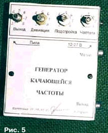
The appearance of the console shown in Fig. 5 (control knobs with axes variables resistors temporarily removed).
Literature
Author: N. Herzen, Berezniki, Perm region.