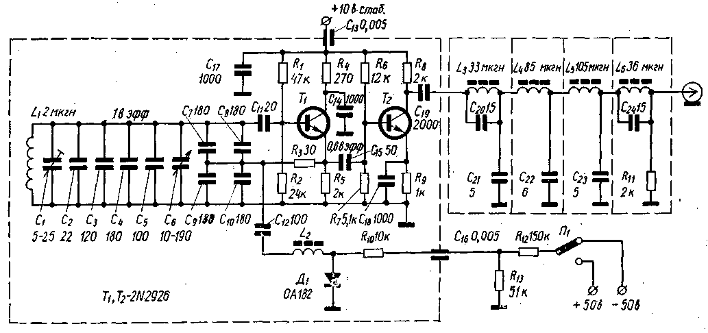
(click to enlarge)
Careful temperature compensation circuit is enabled to reduce the drift of the oscillator frequency to 200 Hz in the temperature range from +10° C to +50° C.
VFO is made of two transistors, wherein the second transistor (T2) serves as a buffer stage. Load buffer stage is a low pass filter with a cutoff frequency of 6 MHz.
In the scheme provided by the oscillator to change frequency when changing sideband in SSB mode, which allows not perform fine-tuning of the transceiver when changing from VSB to LSB and Vice versa. The frequency shift is carried out using a diode key made the diode D1 and the parallel connection of the capacitors C9 and C10 of the capacitor C12 in the VSB mode.
To increase the stability of the VFO circuit is mounted on a chassis made of aluminum sheet with a thickness of 3 mm.
The capacitor C2 has a positive TKE, C3-C5 and C7-C12 - zero. Coil L1 is wound on a ceramic frame, L2-L6 - frames with ferrite cores.
As D1 can be applied diode D. T1,T2 transistors CTA-V.
Literature
Publication: N. Bolshakov, rf.atnn.ru


