


")

Very popular with radio Amateurs use a compact generators test signals useful for testing and developing receivers and sound-reproducing equipment. Offer another similar design generator, wherein an expanded set of fixed frequencies.
Industrial and homemade radio receiving apparatus contains paths 3H and if, moreover, the frequency inverter have different meanings: 455 kHz - in import and 465 kHz domestic receivers for AM signals; 5,5, 6,5 and 10.7 MHz in FM receivers signals. In the magazine "Radio" has published scheme generators-probes for check paths 3H and FC [1-3]. Usually, they give out two signals - 3H and modulated by the if signal with one of these frequencies. So we don't have make a few probes, the proposed generator is provided switching frequencies. It is also used to check almost any instrument, including audio circuitry of TVs.
The oscillator circuit of the probe shown in Fig. 1.

The audio frequency generator is assembled transistor VT1 scheme with phase-shifting RC-circuits (capacitors C1 - C4 and the resistors R1 - R3). The emitter-follower transistor VT2 unleashes the generator from the load, the RF generator. Last performed on the VT3 transistor. Instead of a resonant LC-circuits in the generator are compact piezoceramic filters FC ZQ1 - ZQ5 from radios or televisions. Filter corresponding to the desired FC, is selected by the switches SA1 (FM or AM) and SA2 (the specific value of the inverter). In the situation 3H no filter and not included the RF generator is not working. In this case, receives only the signal 3H.
The collector voltage of the RF generator varies in time with the oscillations 3H, by the way, is the modulation of the RF signal. The positions of switches "455" and "465" amplitude modulation occurs with a depth of 30…40%. In the provisions "5,5", "6,5" and "10,7", in addition to amplitude, a spurious frequency modulation, it is used when testing circuits FM receivers. Parasitic FM contribute to high generation frequency and wide bandwidth piezophiles.
Modulated RF output signal is supplied to the emitter follower assembled on the transistor VT4, which greatly attenuates the effect of the load (check nodes) on the RF generators and 3H. Variable resistor R8 set the required output level. Coupling capacitors C7 and C8 generator output is toggled by the button SB1. In shown in the diagram the position of the switch SB1 through a capacitor C7 to the relatively small capacity pass only the modulated RF signals. When the switches SA1 and SA2 set to "34", button SB1 connect a capacitor of large capacity C8. Power to the probe is served from the power supply check the equipment. The voltage may be in the range from 3 to 12 V.
Generator-probe assembled on the Board of Micarta or fiberglass. Location of parts and the connecting conductors shown in Fig. 2. If the Board made of foil material, the pattern can be made the printed circuit Board. After fabrication cost is placed in any suitable enclosure, for example, the mesh generator field GSP-1.
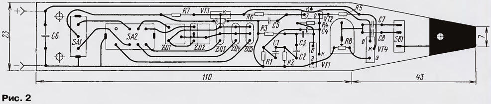
(click to enlarge)
Transistors VT1 - VT4 can be replaced KT3102 or CT with any letter index, transistors VT2 and VT3 it is advisable to choose one with the highest coefficient current transfer. For RF generator you can use any of piezoceramic filters from domestic or imported equipment with suitable frequencies.
The switch SA1 is applied type PD9-1, SA2 - A21-2 button SB - 1 MP-7 or another small. All resistors - MLT-0,125 (MLT-0,25), capacitors - KD, KM, K10 or other small. Resistor R8 - LMS-0.15 or SP-3-386. In as an output pin X1 used needle soldered to the pad on the Board (on the right in Fig. 2) and the contact x2 is the wire on the other end of which is soldered clamp type "crocodile".
The establishment of the generator-probe begin with installation mode of the transistor VT1. It the collector voltage should be 1.5 V when the supply voltage is 3 V. For installation choose the collector voltage of the resistor R4. After that check the presence of generation when changing the voltage from 3 to 12 V. Then fed capacitor C3 (3H generator when it stops working), serves the voltage power 3 and In the selection of resistor R7 achieve the occurrence of HF generation all fixed frequencies, i.e. when any of the piezoceramic filter. If any of the switches SA1 and SA2 generation not occurs (this happens most often in the "10,7"), choose a resistor R6 and then again check the operation of the RF generator at all frequencies.
To verify the presence of HF generation is possible by connecting to the output of the probe high frequency oscilloscope, a voltmeter, a simple detector with measuring head or frequency. In the latter case is checked at the same time and frequency generation. Then establish into place the capacitor C3 and, if you have an oscilloscope, check the quality of the modulation RF signal.
Work with a simple probe. If you check the amplifier 3H, switches SA1 and SA2 is set to "3H", press SB1 and a signal probe 3H X1 alternately to check the various stages of the amplifier, not forgetting to set the level of the signal by the resistor R8. When checking the HRC various instruments select the required frequency switches SA1 and SA2, button SB1 is pressed. Feeding the signal to the input of the HRC after the filter first the primary selection, and then to him, convinced of the passage of the signal through filter and HRC. Otherwise, the Commissioner is checked Pataskala.
Literature
Author: A. Sinchenko, Ozersk, Chelyabinsk region.