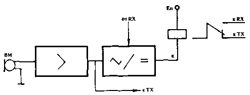
Fig. 1
If you have a sound signal relay K, the commutating circuit radio station for reception or transmission. Sometimes in the Converter circuit to avoid tripping the VOX system from the dynamics of the injected signal from the VLF receiving part. In such schemes typically use Electromechanical relays, the disadvantages which should include contact bounce, delay of response, high noise when switching, high power consumption and low reliability.
System MultiVOX (Fig.2 - 5) has high performance and reliability, small power consumption and can be used on collective radio stations for operator training. Particularly effective application of the system MulliVOX in competitions (multi operator - single transmitter, multi operator - transmitters).
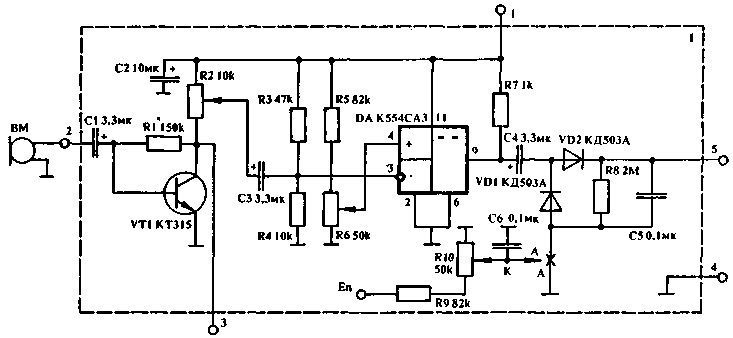
Fig.2
Scheme (Fig.3) consists of n identical channels VOX (Fig.2, block 1), signals from which are received at the switching unit (Fig.3, 5, block 2). The switching unit 2 transmits the control signals from the channel, which is involved at the moment.
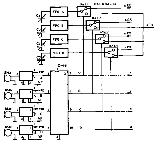
Fig.3
Accidental appearance of a signal on any other channel for the passage of control signals is prohibited by the switching unit and the radio is receive-only. So, if radios operate on four operators, three of them sniff the air, looking for correspondents range (ranges); and one conducts radio communication with another correspondent. After another radio operator calls following correspondent, and the rest work at the reception. It is assumed that each operator has a generator a smooth range (VFO), the part of the receiving path. When working on the transmission in the transmit section is enabled only one of the generators and simultaneous work on two operators work on two frequencies) is excluded.
Block 1 (Fig.2, 3) is a conventional VOX consisting of a microphone preamplifier transistor KT315 (or low-noise analog) , the output of which (pin 3) low-frequency (LF) signal is sent to the shaper single-sideband signal. From the preamplifier the signal LF is supplied also to the comparator is made on the chip CSS. Instead of the load resistor R7 may be included relays, for example, RES-9, parallel to the winding of which you should connect the capacitor to 100 UF. For individual stations, the control signal can be removed from the output 5 of the block 1 without using the switching unit 2.
Potentiometer R2 sets the sensitivity of the VOX device for speech signal R6 - threshold comparator. To increase the level of the output control signal (pin 5 of block 1) by increasing the DC component in the output signal with 0 to 3 - 4B, a block diagram can be detached from the common wire and is connected to the engine of the potentiometer R10.
Scheme MultiVOX (Fig.3) allows to work with any remote control (microphones BMa...BMd). The circuit of the VFO switch signals (DA.1...DA1.4) are shown conventionally. Switch channel can be used for switching analog signals, including a sufficiently high frequency, with an amplitude (peak-to-peak) to 50% of the supply voltage of the chip (3-15 In - C, C), or switching the buffer of the cascades and powerful relay circuit DC.
The number of simultaneously switching circuits can be increased in parallel control electrodes of the switches (Fig.3, additional outputs a...d). Between control inputs of the switches X and Y can be included RC - elements and diodes that will allow for various time actuation of the respective switches.
Options switching blocks 2 shown in Fig.4A (for two operators) and Fig.4B (four operators).
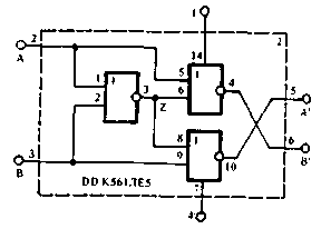
Fig.4A
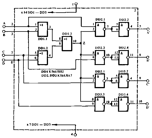
Fig.4B
When working Telegraph control signals from the keys (electronic keys) can be fed directly to the corresponding inputs of the block 2.
Literature
1.Bunimovich, S. G., Yailenko L. P. Technique Amateur single-sideband radio. - M.: DOSAAF, 1970.-S.
2. Analog and digital integrated circuits: Reference book/ S. V. Jakubowski and others - M.: Radio and communication, 1984. -432 p.
Author: M. Shustov, Tomsk; Publication: N. Bolshakov, rf.atnn.ru


