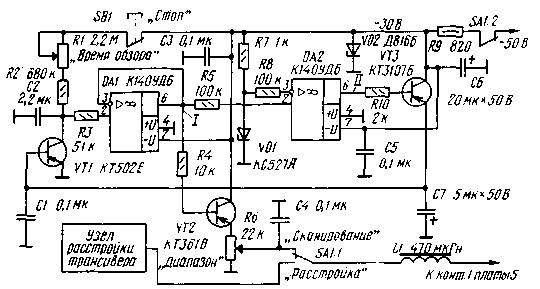
Fig.1
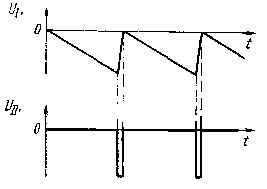
It is made on transistors VT1-VT3 and operational amplifiers DA1 (repeater), DA2 (comparator). When the switch SA1 to "Scan" the power to the varicap GPA transceiver comes with a host of detuning, and the emitter repeater scanner. In point 1 tab 5 of the transceiver is served sawtooth voltage of negative polarity amplitude of about 27 In (Fig. 2).

Fig.2
At the same time through the contacts SA1.2 receives a supply voltage (-50 V) transceiver with the scanning device and is stabilized by a stabilization element VD2 (chosen with a voltage close to 30 In). When you enable scanning device begins to charge the capacitor C2 (through the normally closed button contacts SB1 and resistors R1, R2). As long as the voltage across it has not reached -27, at the output of the comparator DA2 voltage will be about 0. Transistors VT1 VT3 and thus closed. When the voltage at the capacitor C2 becomes equal to -27 V, the comparator output will appear a voltage of about -30 V (Fig. 2). Transistors VT3, VT1 opens, and the capacitor C2 is rapidly discharged through the open transistor VT1. After that, the transistors VT3, VT1 is closed and the charging process of the capacitor C2 again.
Thus, the output of the scanning device will be formed sawtooth voltage of negative polarity. Changing the position of the slider of the resistor R6 is used to adjust the amplitude of the sawtooth voltage from 0 to 27, and thereby the scanning range. In upper circuit on the position of the slider of the resistor scanning range maximum is 50 kHz. Resistor R1 is possible to vary the time constant of the charging circuit of the capacitor C2. In upper circuit on the position of the slider of the resistor R1, the charging time is a maximum of 30 s, the lower minimum, about 6 p. If during the scanning process click on the button SB1, the charging circuit of the capacitor C2 is broken and the varicap GPA transceiver receives constant negative voltage corresponding to the moment of pressing the button. In the described device can be used, in addition to those indicated in the diagram, operational amplifiers COD, COD, KMOD, COD, CRUD, etc. Transistors VT2, VT3, you can use any of the series KT361, CT, CT, etc., the Capacitor C2 - K73-17.
Literature
Author: B. Siskin (UB5BCJ), Ternopol; Publication: N. Bolshakov, rf.atnn.ru


