To save You from a premature heart attack and save Your family budget, I propose to use in experiments, a simple device that will prevent such situations. We are talking about protecting the transistor current.
To protect the transistors in the power circuit of the collector include resistors that limit the current during overload. The degree of protection of the transistor is directly proportional to the resistance value of the resistor. If you increase the resistance there is a power loss of the cascade, deteriorating the linearity, useless power dissipated on the resistor. So choose a compromise value of resistance that is acceptable for a particular case.
Even worse is the case in microwave technology, where the voltage between the electrodes of the transistor depends on the capacitance of p-n-transition of disabled children. During pulsed modes (SSB, CW) current of the cascade varies from 0 Yes maximum value. The voltage at the collector will vary due to the drop across the resistor. This causes a change in the tuning of the resonant circuits, the amplified signal is "scattered", appears self-excitation cascade. From this it follows that the power of the collector circuits of transistors necessary to use more stable voltage and current protection to carry out by means of threshold current limiter.

Fig.1
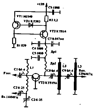
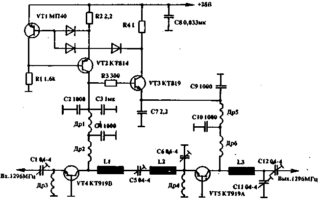
The operation of this device, consider the example of the mixer circuit TX band 1296 MHz (Fig.1) when the voltage across the terminals of the resistor R2 reaches a value at which opens the diode VD1, the VT1 transistor opens, VT2 is closed, the voltage will drop. The application of the protection circuit allows to obtain a linear mode of operation of the mixer and to protect the transistor when pumping at the input 144 MHz. In the two-stage amplifier for 1296 MHz is applied to the protection circuit that reduces the voltage on both sides of the cascades in excess of a predetermined value of current of one of the transistors of the amplifier (Fig.2).

Fig.2
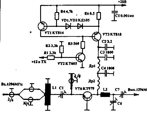
The tripping current speed is governed by the number of diodes and smoothly the selection of the resistors R2, R4. Some of the transistors (for example, CT, KT), due to their design, have an initial quiescent current. In receive mode and when working on other bands it is necessary to remove the voltage of the cascade. This operation performs a device, scheme of which is shown in Fig.3.

Fig.3
In addition to switching voltage scheme provides protection of the cascade current.
Author: V. Petrusenko (RB5EC), Dnipropetrovsk; Publication: N. Bolshakov, rf.atnn.ru


