


")

UHF schematic diagram of which is shown in Fig.1, features a large and stable gain Ki (several thousand ) and small consumption and high stability characteristics [1].
The DC of the transistor VT1 is connected by a diode (base and collector shorted through the inductor L1). The whole scheme DC is an improved current generator Wilson deep EP current. Therefore, the modes of operation of all transistors are stable and do not depend on temperature and supply voltage (if it is greater than 2 In) .The collector currents of VT2 and VT3 are the same and are set by the resistor R1, the value of which is determined by the formula: R1=(u pit-2Uбэ)/IK, where the Uбэ= 0.7 V for silicon transistors; I is the desired current collectors VT2, VT3.
AC-coupled circuit is an amplifier MA-MA-MA with the largest coefficient in comparison with other circuits of switching transistors in trendresearch amplifiers.
The first stage of amplification is performed on the transistor VT1, a L1 provides the offset. The VT1 is equal to zero voltage collector-base of this transistor. This however, does not affect its reinforcing properties, since voltage collector-emitter IKE= 0.7 V, low-power silicon transistors are much more saturation voltage gap of 0.1-0.2 V.
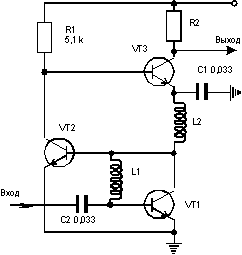
C1,C2= 0.033 µf, L1,L2= kg, R1= 5.1 kω
With such a low voltage IKE active mode VT1 is stored only Yes as long as the amplitude of the alternating voltage at its collector will not exceed 200 mV . However, in this amplifier, it cannot be greater due to the high gain of the subsequent stages in VT2, VT3.
The second stage of amplification to VT2 also made under the scheme with the MA, the amplified signal is allocated to R1. With the collector signal VT2 to VT3 base, the emitter of which is grounded through a high frequency blocking capacitor C2. The amplified output signal VT3 is allocated to the load Z1. which can be used parallel resonant circuit (resonance amplifier) or a resistor (with broadband).
The amplifier has a high and stable gain, non-critical installation and arrangement of the elements. When indicated in Fig.1 the value VT1-VT3 CHAM Uvolt=12V and the resistor in cm as Z1 amplifier covers the frequency range 0.1-20 MHz and Ki=3000. If adjustments are required, Key in a wide range (e.g. AGC) control voltage +1.5… 12 V can be applied to the top terminal R1, releasing it from the plus power supply.
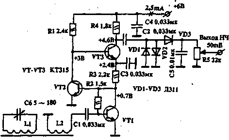
Usage example considered in the UHF receiver of direct amplification in the MW range are shown in Fig.2. Magnetic antenna WA1 performed on the core with permeability of 400 0 8 mm L1 contains 90 turns of wire PELSHO 0.1, a L2 - 3 turns of the same wire.With coil L2 connection the received signal is input to the UHF, similar to that described, with the only difference that, for simplicity, instead of chokes included registry R2, R3. Input from UHF to Ku=6000 at u n and m=6 V. the Detector is made on the diodes VD1-VD3, which must be germanium. The receiver keeps working when the voltage to 1.6 V.
Literature
1. G. Utochkin. I. Goncharenko. The high-frequency amplifier. Application USSR No. 4649488/09, Decision vniigpe on issuance of a certificate of copyright from 23.11.89
Authors: G. Utochkin Ryazan, I. Goncharenko (RC2AV) Minsk; Publication: N. Bolshakov, rf.atnn.ru