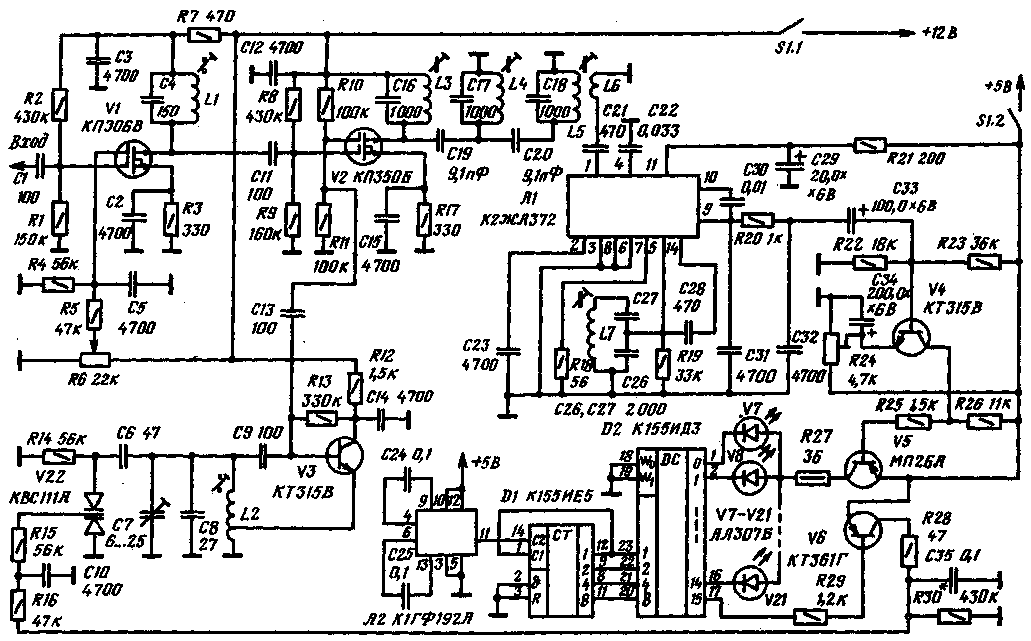
Searching for the signals of stations on the side of the tuning frequency УLW transceiver, can be facilitated and enriched it with a simple panoramic indicator (see illustration). It allows to indicate the presence of stations in the band of ±40 kHz. Information is displayed by the led indicator on the 15 LEDs. Each of them controls the band width of about 5 kHz. When the signal appears in the overview strip lights up the corresponding led. The brightness of its light can be roughly estimated signal strength.
The indicator consists of the receiving part and host scan. The receiving portion includes an input amplifier, local oscillator, mixer, if amplifier, detector and amplifier WOOFER, host sweep - master oscillator, a pulse counter, decoder and led indicator. The input amplifier is assembled on the transistor V1. Its load - circuit L1C4, tuned to a frequency FC of the transceiver, in this case equal to 8750 Hz. The gain of the stage is controlled by resistor R6.

(click to enlarge)
Heterodyne performed on the transistor V3. Generated by an RF voltage at a frequency higher than the input if signal. Frequency modulation of the local oscillator is a variable capacitor V22, which includes the sawtooth voltage from the charging-discharging chain R28C35R30.
The mixer is assembled on dfugstore field effect transistor V2. On his first shutter signal from the input amplifier, the second voltage of the local oscillator. Load mixer filter is a concentrated breeding, tuned to an intermediate frequency indicator, which is selected equal to 460 kHz. On the same frequency circuit configured and L7C26C27.
The converted signal is supplied to the if amplifier and detector indicator collected on the chip A1. Circuit AGC circuits are not used. The rest of the inclusion model.
Low frequency amplifier transistors V4, V5. The indicator is not affected by the loss of the DC component, the capacitance of coupling capacitor SZ chosen large enough.
To the collector of the transistor V5 through resistor R27 is connected to the anodes of the LEDs V7-V21. The cathodes of LEDs connected to the outputs "0"to"14" IC D2.
The master oscillator is assembled on the chip A2. It generates pulses with a repetition rate of 400 Hz. After the divider 16 on the chip D1 pulses in parallel four bit code received on the inputs"1", "2", "4", "8" decoder D2, which commutes-LEDs V7-V21. Resistor R27 limits the pulse current through the LEDs and the chip outputs D2.
Every sixteenth pulse at the input circuit D1 output "15" IC D2 appears logical low level via the resistor R29 opens the transistor V6. Thus from the power source through a resistor R28 charging the capacitor C35. With the arrival of the next pulse at the input circuit D1 logic 0 appears alternately at the outputs "0"to"14" IC D2 and, thus, the LEDs V7-V21 serially connected to the transistor V5. Capacitor C35 at this time is gradually discharged through the resistor R30. The sawtooth voltage through resistors R16 and R15 is supplied to the varicap V22. So is a periodic change in the lo frequency and synchronous scan led indicator. Since the capacitor C35 is discharged in each cycle on relatively little, the frequency sweeping is rather linear. For the selected parameters of the circuit of the local oscillator and a sawtooth voltage on the varicap, the magnitude of which is equal to 2 V, the frequency of the local oscillator varies in the range ±40 kHz.
Entrance panoramic indicator connected to the transceiver at the point through which passes a signal with a bandwidth of ±40 kHz. However, there needs to be suppressed signals falling within the bandwidth of the mirror channel indicator. In this case, the frequency 9670 kHz (8750 + [H] = =9670 kHz).If the mount point, this condition is not met, replace the circuit L1C4 should install bandpass filter.
The building block is the set of contours on the above frequency. The bandwidth indicator is determined by the set of contours L3C16, L4C17, L5C18 and L7C26C27, and given the purpose of the panoramic indicator, it is chosen equal to 3 kHz at -3 dB.
Swing band lo frequency within ±40 kHz set, selecting the ratio of the capacitance of the capacitor C7 and inductor coil L2. If you want to reduce the sawtooth voltage on the varicap, you need to include a resistor R30 high impedance. The initial brightness of the LEDs is set by a resistor R24.
Coils L1 and L2 wound on the frames with a diameter of 7.5 mm with podstroechnik SCR-1. L1 contains 15 turns of wire sew-2, 0,27, L2 - 6+15 turns of wire sew-2 of 0.2. The length of the winding coils are respectively 7 and 9 mm. as the coils L3. L4, L7 and L5, and L6 are used, respectively, of the coil III and the FSS the FSS IV from radio VEF-201.
Panoramic indicator is fed from the DC voltage sources 12 and 5 V. the 5 V also serves on the 24-th output circuits D2 and 5-th chip D1. 12-th output D2 and 10th D1 is connected to the common wire.
Author: V. Tereson (UB50BJ), Uzhgorod; Publication: N. Bolshakov, rf.atnn.ru


