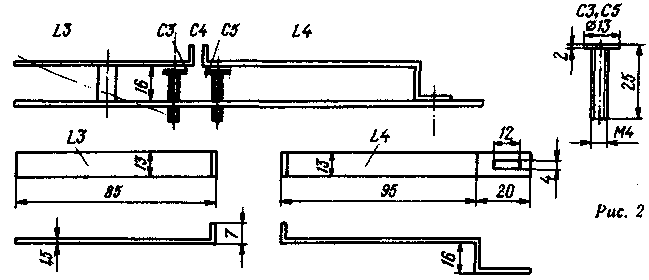
For the manufacture tripler requires a brass sheet of thickness 1.5-2 mm. made of brass chassis size H mm and the details of microwave circuits. The drawings of these parts and the node L3. L4. C2-C5 in the collection are given in Fig. 2.

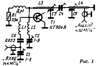
Coil LI consists of 4 turns of wire of 1.5 MG, the winding frame, the winding diameter - 10 mm length - 20 mm; L2 - 2 turns of the same wire, the winding frame, the winding diameter - 9 mm, length 10 mm; choke DR1 contains 10 turns of wire of 0.5 MG, the winding diameter is 3 mm.
In strict compliance with the size of the parts configuring tripler is not difficult. To the output terminal of the tripler is connected at one end ("Piglet") incandescent lamp 6.WH.28A.

The withdrawal from the output circuit is set at one third of the length of the line, counting from the right (under the scheme). Circuit L1C1 tune to resonance at the fundamental frequency of the transmitter, the circuit L2C2 - for the second harmonic, the contours L3C3, L4C5 - frequency tripler.
In conclusion, choose the relationship between the contours and the connection with the antenna on the highest return of energy.
Author: B. Karpov (RI8AAD), Tashkent; Publication: N. Bolshakov, rf.atnn.ru


