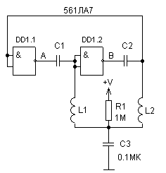
In Fig.1 shows a diagram of generator. At power-up through the resistor R1 starts to charge capacitor C3,as increase the voltage on C3 logic gates are switching in unstable condition, starts the oscillatory process, the frequency which is determined by the parameters sequential circuits C1L1 and C2L2.
In the steady state, when C1=C2 and L1=L2, the voltage on C3 corresponds half of the supply voltage, and the outputs DD1.1 and DD1.2 there is a meander. If the parameters castorocauda elements will change, it will change squarenot signal. Inputs elements DD1.1 and DD1.2 contain protection diodes that shunt LC the circuit, therefore it is recommended connect inputs DD1.1 and DD1.2 with LC circuits through resistors resistance 10K...100K.

Fig.1
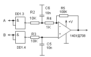
The signal squarenot can be converted to a voltage, for this to the generator through the buffers DD1.3 and DD1.4 connect the integrators (Fig.2). Such scheme can be used to measure the parameters of the capacitors or inductors. Change the voltage at the output of op-amp will be proportional to the change settings or L.

Fig.2
This generator was used to measure small displacements, this castorocauda the circuit had the following parameters C1=C2=PF, coils L1 and L2 wound onto frame diameter 8mm with trimmers of ferrite, and contained in 40 turns of wire PEL-0.3, sensor served podstroechnik one of coils, free peremeschalsya in the frame, the operating frequency is about 1MHz, supply voltage 12V. If move both podstroechnik, get the differential sensor.

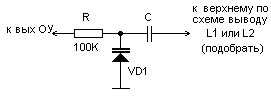
Fig.3
To the output of the operational amplifier you can connect the varicap (Fig.3), included in one of LC circuits, that would have formed a negative feedback - get a scheme with automatic adjustment signal the error is removed from the output Oh.
Author: Dr. Mabuzu; Publication: N. Bolshakov, rf.atnn.ru


