


")

Volkoder - a device that changes some value in depending on the rotation axis. Such a thing is found, for example, in roller mouse or at the music center. In fact, by itself, volkoder fairly simple, but we will complicate the task of those that won't use a microcontroller, like this practiced in all industrial designs. Volkoder interesting in that it are many techniques used in digital and analog electronics. So the TOR: to develop a device that changes the output voltage in the range of 0 - 3V, linear dependence of the rotation angle of the axis. Change the voltage must be reversible, with the number of gradations of not less than 80. Output signal to be false he isolated operating voltage of the device (galvanic isolation). Full the increase/decrease of stress occurs when the angle of axis rotation from 0 to 1440 degrees (4 turns). Device should continue to operate in the range of supply voltage from 8 to 15V. To provide digital readout of voltage.
1. Why to start?
Let's define what we want:
A. first the "head" of the device will be digital because it will to count pulses generated by rotating a handle.
B. counting of pulses must be reversible, because the resulting value decreases and increases depending on the direction of rotation of the handle.
V. at least 80 gradations of the output voltage. Means for the voltage we need at least 8 bit binary code (80[10] = 1010000 [2]). 80 gradations for 4 turns, then per rotation, the handle must issue 20 pulses. One pulse every 18 degrees.
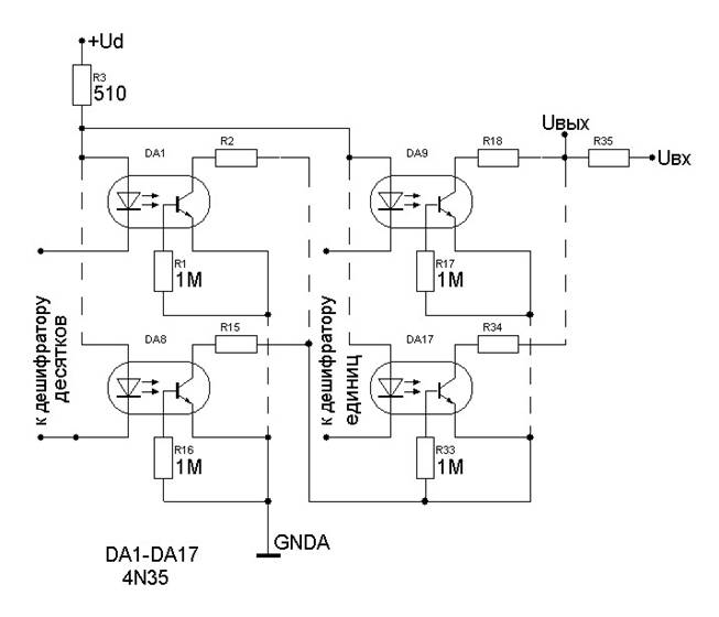
For galvanic unlock output voltage, V Converter cascade (digital --> analog) will need use optocouplers.
D. At the working voltage of the chip series C and 564.
E. Digital display - simple knot, but it will take another 2 decoder to 7-segment code.
2. Now let's try to describe the algorithm works
- When the output is 0.
- IF the output is 0 And there is a pulse from the sensor And the handle is rotated clockwise - add 1 to the output code.
- IF the output is 0 And there is a pulse from the sensor And pen is rotated counterclockwise, it is not to take any action
- IF the output is 1010000 pulse from the sensor And pen turns clockwise - not to take any action
- IF the output is 1010000 pulse from the sensor And pen is rotated counterclockwise, subtract 1 from the output code
- IF result is a number greater than 0 and 1010000 And has the momentum with the sensor And the handle is rotated clockwise, add 1 to the output code
- IF result is a number greater than 0 and 1010000 And has the momentum with the sensor And the handle is rotated counterclockwise, subtract 1 from the output code.
- IF there is no pulse from the sensor is not to take any action.
3. Draw up a block diagram of the device
It is obvious that the mechanical part has to inform about the the rotation and its direction. So the sensor should produce 2 signals. In the result is that the device shall consist of a reversible counter, block alignment interchange and digital to analog Converter.
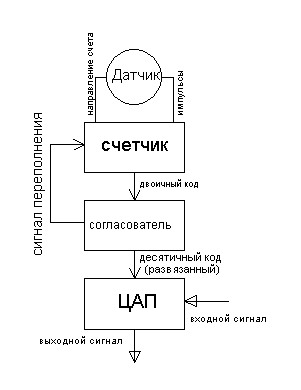
The Aligner should display indication and ban folding counter (if high) or subtract (if obtained a minimum).
4. The constructed sensor
Water poured enough, now we can talk more subject. Mechanics dependent on electronics, and electronics from mechanics, so consider the sensor as a single unit. It is quite clear that use optical sensor much more convenient than a pin, so we came to a drilled wheel. To obtain pulses that easy, I had to determine the direction of rotation. There two ways: use two optocoupler (emitter + receiver) placing them in such a way that is illuminated first, one receiver, and then the second. Or use the flap, moving on the same axis as the wheel (the torque produced by axis, must exceed the weight of the damper and it should not rotate under its own the weight).
This flap is rotated synchronously with the wheel to a certain angle (not more than 4.5 degrees to either side) and opens/obscures more (Gating) of the photodetector. This option greatly complicates the mechanics, though very simple in circuitry implementation (the logical "And"), so back to the first option. Now count up time diagrams of signals, generated by the sensor.
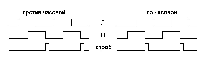
As can be seen from the figure, the signals of the receivers are displaced in phase by 90 degrees. This is easily achieved by placing the receiver next in line. Thus, when the hole passes over the receivers, first illuminated first the receiver, then both, then the second.
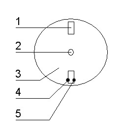
Assume that the wheel (3) rotates clockwise around axis (2). When the hole (1) suited to the optocouplers, First illuminated right the receiver (5), then both, then only the left (4). And this is repeated for 20 times one rotation. From these plots it is seen that the rear edge from the right the receiver is formed a gate signal. On it we will build the resulting sensor signal: first, it is generated only in instance when covering receivers, and secondly, it perfectly describes the direction of rotation.
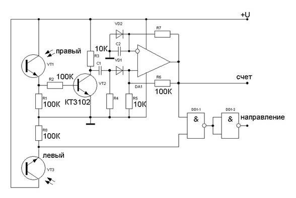
Coinciding with the momentum of the left sensor when rotating a clockwise direction, it gives you the opportunity to highlight the positive momentum with the help of logical element "And". To obtain this wonderful momentum we need the single vibrator to obtain the desired duration. The original front negative so it must be inverted. Let's try to sketch a diagram: loop EP the single vibrator is calculated based on the maximum wheel speed - duration Gating pulse must not exceed 1/4 of the period of the "right" signal. Chain С1R4 is calculated on the basis that formed its momentum should be 0.1 Tstr.
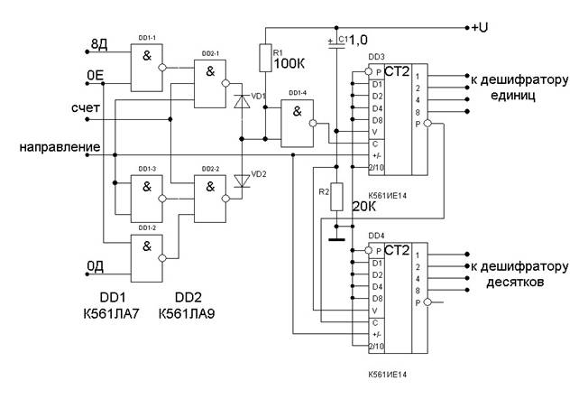
5. Let's build the simplest block in the device counter
Wanted to draw a diagram on the triggers, but it seemed to me absolutely monstrous mockery of electronics. If interested, scheme down counter the triggers can be found in any Handbook on digital chips. Therefore, our task is reduced to the standard counter from traditional series CMOS. So we will define the requirements for the counter:
- Power supply 8-15V
Reverse
Such conditions satisfies CIE
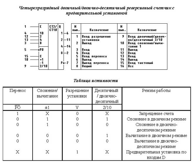
As seen in the picture, the counter has a preset inputs. Using these inputs we can quickly put on the output required voltage, causing external RAM corresponding code. Of course in RAM should be created a Bank of stored levels. In TK not specified in this the possibility, therefore, use the preset inputs for reset. As there is the entrance of the prohibition bill (RO). But to use it to protect from volkoder overflow will not work. The fact that this input does the blocks and schetchik don't allow him to even consider in a free direction, and we need to reaching a critical level in one direction-free direction remained free. Therefore, the overflow signal we highlight after the decoder. This signal we will be Gating input "C".
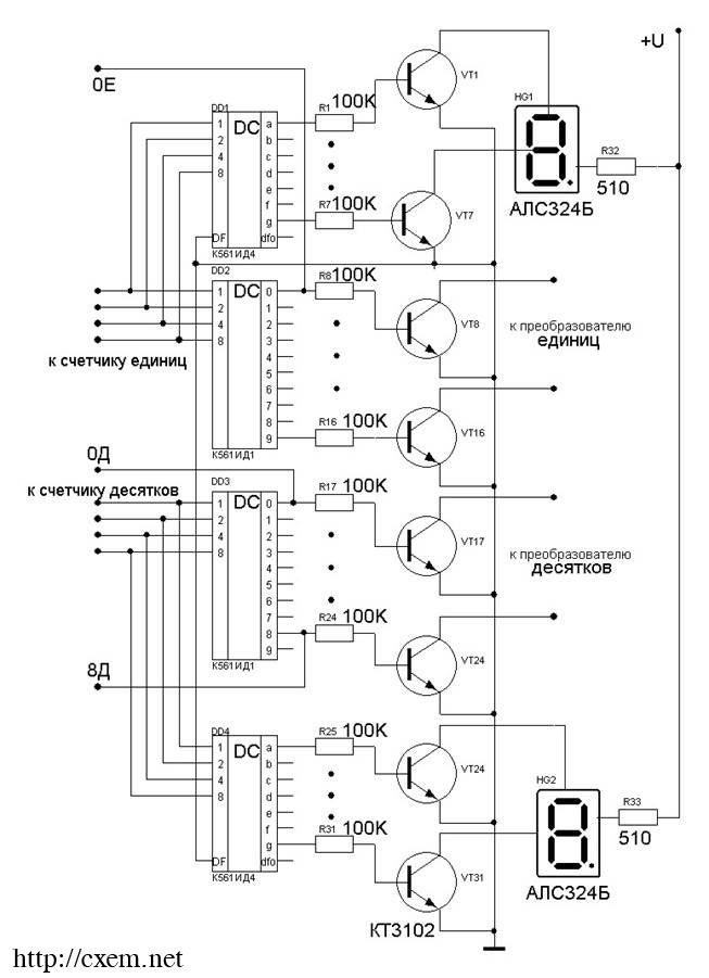
6. Now you can do a relatively simple, but bulky knots decoder and digital-to-analog Converter (DAC)
So, for example, I got a decoder. Nothing sly: mass decoders and transistor switches to control the optocouplers and semiconductor LED indicators-OA. The decoders are quite traditional: KID - binary code Converter to decimal and KID - Converter binary code to seven segment.
DAC will be built in a similar way. The only thin moment - definition of ranges. Comparison of boundary adjustment and dozens of units. We have 7 tens and 10 units. Divide the total output voltage 80 grades: of 0.04 is obtained. Multiply by 10 - turns of 0.4. Hence, isolated discharge regulates the voltage within 400mV. Consequently, the remaining 2.6 In managed dozens. Now you only have to pick up the resistors, switchable opto keys and, with their help, to build the desired scale adjustment.
Here is turned out to be.
Author: Paul A. Ulitin (Soundoverlord); Publication: www.cxem.net