


")

Reducing the weight and size and increase the efficiency of power supplies is one of the urgent tasks in the design of modern of electronic equipment. Most simply, this task is solved by replacing traditional rectifier (with bulky mains transformer and capacitive filter) high-frequency transducer with subsequent rectification high-frequency voltage.
Schematic diagram of the power source shown in Fig. 5.7. The output block receive bipolar voltage 2x27 In load current up to 0.6 A. the Amplitude of the output ripple voltage at maximum load current does not more than 30 mV.
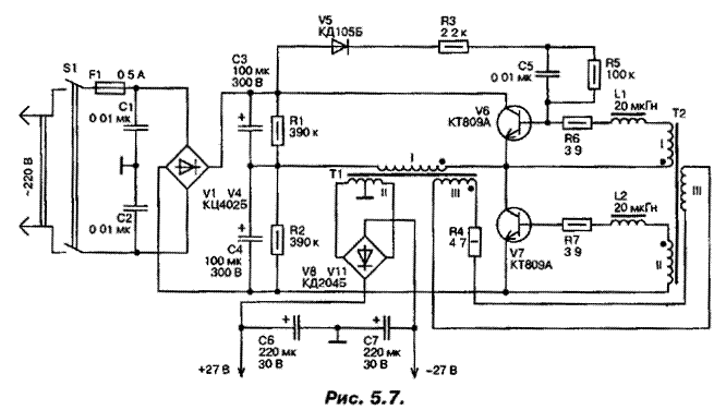
The mains rectifier is assembled on the diodes V1…V4. Converter the rectified voltage transistors V6, V7 and the transformers T1 and T2, and the voltage rectifier high frequency diodes V8…V11. Working the frequency voltage Converter 22 kHz. Capacitors C1 and C2 are required for protect the mains from interference with the operation of the Converter. Resistors R1 and R2 together with capacitors C3, C4 are the primary filter and also a divider voltage for the Converter. Chain V5, R3, C5, R5 serves to facilitate run the generator Converter. Filter the rectified high-frequency voltage are the capacitors C6, C7.
The use of two transformers in the voltage Converter enabled to increase its efficiency. In conventional converters with one last transformer works in saturation mode. In the Converter with two output transformers the transformer operates in a linear mode at a much lower induction than in the mono-transformer Converter. This allows to reduce the loss in the core, and thus improve the efficiency of the Converter.
Saturating transformer T2 is calculated only on the power consumed the base circuits of transistors V6 and V7 and therefore is small in size. To disadvantages converters with one transformer should include the fact that in the switching of transistors appears significant release of collector current. In the Converter with two transformers this release almost missing, greatly reducing the so-called dynamic losses and increases the overall efficiency of the Converter.
The link between the transformer windings III leads to the fact that in the right time of the transformer T2 is in saturation mode. It is necessary for to occur of the conditions of operation of the Converter, which are mentioned above. Transformer T2 is a switching element included in the base circuits of transistors V6 and V7. When saturation of the transformer T2 its magnetizing the current rapidly increases, thereby increasing the voltage drop across the resistor R4 and decreases the voltage on the coil III, and hence on the windings I and II, which leads to a decrease of the base current and the output open transistor in the active region and the switching transistors. Switching frequency determined by the time of reversal of the saturating core transformer T2.
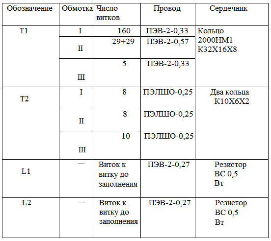
Inductors L1 and L2 provide the opening delay of one transistor as long while the other is completely closed. This is necessary to eliminate currents through and reducing losses in the switching transistors. Data transformers and chokes are placed in table. 5.1.
Correctly assembled power unit does not require the establishment.
Author: A. P. Seman