The power supply 180 W, output voltage 2x25 In at a current load 3.5 A. the Magnitude of the ripple in the load current of 3.5 And not more than 10% for the ripple frequency of 100 Hz and 2% for a frequency of 27 kHz. The output impedance is not exceed 0.6 Ohms. The dimensions of the block 170x80x35 mm, weight 450 g.
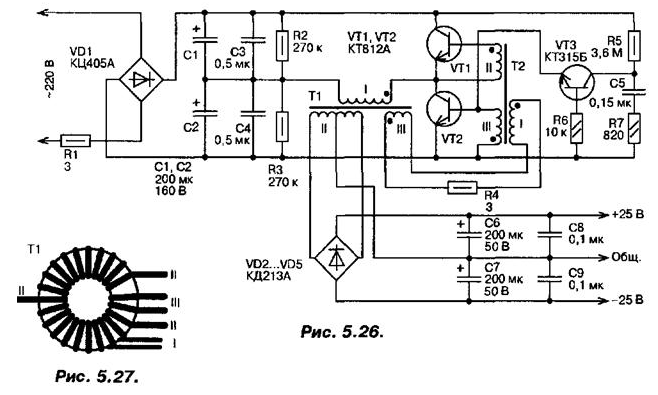
The supply circuitry represented in Fig. 5.26.

After rectification by a diode bridge VD1 is the voltage filter capacitors C1...C4. Resistor R1 limits the current charging capacitor filter flowing through the rectifier diodes in the unit is switched on. The filtered voltage is supplied to the Converter voltage built on a half-bridge inverter transistors VT1, VT2. The Converter is loaded by the primary winding of the transformer T1. transform voltage and electrically isolating the output of the block from the network AC. The capacitors C3 and C4 prevent the penetration of the RF network interference from the power supply. Half-bridge inverter converts DC voltage to AC rectangular shape with a frequency of 27 kHz.
The transformer T1 is designed so that the magnetic circuit is not saturated. Self-oscillating mode of operation provided by the feedback circuit, the voltage which is removed from the winding III of the transformer T1 and is supplied to the coil I auxiliary transformer T2. Resistor R4 limits the voltage at the winding I of transformer T2. The resistance of this resistor depends certain limits conversion frequency.
To ensure reliable start up of the Converter and its stable operation is the start node, which represents a relaxation oscillator transistor VT3, working in avalanche mode. When the power is turned on through the resistor R5 begins to charge the capacitor C5 and when the voltage across it reaches 50...70 V the avalanche transistor VT3 is opened and the capacitor is discharged. The current pulse opens the transistor VT2 and starts the inverter.
Transistors VT1 and VT2 are installed on a heat sink with an area of 50 cm2 each. Diodes VD2...VD5 is also provided with a plate heat sinks. The diodes are clamped between the five dural plates size 40x30 mm each (three medium-sized plate 2 mm thick, two extreme 3 mm). The whole package tighten the two screws. MH, bolts passed through apertures in the plates. To avoid short-circuit plates the screws they put on segments of PVC tube.
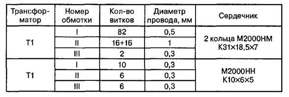
Winding characteristics of transformers are given in table. 5.4, location the windings of the transformer T1 is shown in Fig. 5.27 (primary winding wound on the perimeter of the ring, the figure is not shown).

The wire windings - sew-2. To facilitate starting of the Converter winding III of the transformer T1 should be located on the site occupied by the winding II. Winding insulation in the transformers comply with a tape made of varnished cloth. Between windings I and II the isolation transformer T1 three-layer, between the other windings transformers - single layer. Transistors CTA can be replaced by CTB, CTA, CTA, CTU, diodes KDE - CDB. Correctly assembled power pack usually in establishing't need it, but in some cases may to require a selection transistor VT3. To check its efficiency to temporarily disable the output of the emitter and attach it to the negative terminal of the the network rectifier. Oscilloscope to observe the voltage on the capacitor C5 is the sawtooth signal by the scale 20...50 V and a frequency of a few Hertz. If the sawtooth voltage is not present, the transistor needs to be replaced.
The application of this power source does not preclude the necessity of blocking circuits power amplifier AF the big capacitors. The connection of such capacitors even more reduces the pulsation level.
Author: A. P. Seman


