


")

At independent manufacture of small electronic devices with powered by a network of ham radio operators are often faced with a situation where mains transformer is only noticeable heating element the device that dissipates as heat capacity, sometimes several times exceeding useful. The fact that the industrial transformers the manufacture, having the appropriate dimensions and voltages, sometimes executed so "economically" that even the idle current causes increased heating.
Especially often this lack transformers have made in South-East Asia [1]. They are more suitable for countries that use the network voltage 220 V with a frequency of 60 Hz, but for normal network operation with a frequency of 50 Hz the number of turns of the winding network is insufficient.
In Fig. 1 shows the dependence of the no-load current of the supply voltage some transformers. Curve 1 corresponds to the transformers from universal adapters "SANWALL" and "BELLSONIC" power of 5 watts, with a maximum load current 300 mA output voltage 3…12 V, having the magnetic cores cross-section of 1.4 cm2. For comparison, curves 2 and 3 transformers domestic the production of TP - 133 TP - 321, whose cross-sectional area magnetoroton 2 and 1.6 cm2, respectively.

Given that the supply voltage, especially in the cities, maybe a long time to exceed 235, and the increase in voltage above the nominal causes a disproportionate increase in the no-load current, to the use of such transformers, especially in devices designed for continuous operation unattended (timers, temperature controllers, antenna amplifiers, etc.), should be approached with great caution.
In this situation there is. You must include active or reactive the ballast resistance in the circuit of the primary winding of the mains transformer for reduce the voltage 20…30 V. the load Current and heating the transformer is considerably reduced. Of course, this reduces secondary the voltage and wattage of the transformer. However, if the power consumed device, much less overall power transformer, it is quite valid.
Usually for such purposes use resistors or capacitors [2]. Main the disadvantage of resistive ballast - heat, which limits the use of such method. Moreover, the voltage across the primary winding meleagrou proposed transformer and the resistor have different phases (phase shift can reach up to 70…80 degrees), therefore, the voltage across the resistor is usually higher expected. For example, if the line voltage is 220 V and the primary winding of not-loaded transformer 195 In the voltage across the resistor can reach 45 V. When the load of the transformer is increased to values close to the nominal phase shift is reduced to almost zero.
Capacitive ballast practically does not emit heat, but as practice shows, capacitors are most appropriate to apply when the voltage on the windings the transformer is necessary to reduce by more than 25…30 %. In any case, if capacitors, you need to ensure that when the load changes and the supply voltage in the circuit of the primary winding does not occur resonance phenomena, when the voltage at the transformer can increase dramatically [3].
In the case of inductive ballast of such phenomena does not occur since the phase voltages are almost identical, the heat released only on the active resistance of the winding of the ballast, which is several times less than that of the equivalent to the ballast resistor.
As inductive ballasts convenient to apply electromagnetic relay DC operating voltage of more than 20 In, for example, PCM, RES RES9, RES etc to reduce their dimensions, the relay can be disassembled and used only the coil with Manitoba-switching. To eliminate the chattering of the armature of the relay should be locked in energized condition by flexion or with a pointed matchsticks and glue. If you select relay, you must consider the maximum current in the primary circuit of the transformer, which must not exceed the nominal operating current the relay.
Curve 4 in Fig. 1 shows the change in the no-load current of the transformer (dependence 1 in Fig. 1) with inductive ballast (relay PCM-2 voltage 24 In with the winding resistance of 750 Ohms, rated operating current 35 mA). In Fig. 2 shows the load characteristics of the same transformer (output voltage rectifier with filter): curve 1 - without ballast; 2 - with inductive ballast (relay PCM-2); 3 - equivalent (for the load current 20 mA) resistive ballast - resistor of 3 ohms and a power of 4 watts.
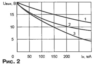
High load capacity of a transformer with inductive ballast for compared to an equivalent resistive due, apparently, reduced the inductance of the ballast due to the saturation of the magnetic circuit by increasing the current flow. This is evident by the characteristic change of the curvature dependence 2 in relation to schedules 1 and 3 load current 150…200 mA.
Literature
Author: V. Andreev, Togliatti, Samara region.