Consider a number of power sources with application integrated voltage regulators.
Widespread three-terminal integrated stabilizers which are designed to provide different levels output voltages and currents. In the scheme described in this paragraph, is used integrated voltage regulator 7805. The last two digits in the designation indicate the value of the output voltage. An even number at the beginning of the designation, two digits - 78, shows that the stabilizer is designed to receiving a positive output voltage relative to a common output the integrated circuit; an odd number indicates a negative output the tension. Therefore, the designation 7905 suggests that three-terminal the stabilizer provides a negative output voltage of 5 V. Similarly this index 7812 shows that the stabilizer is designed to produce positive output voltage of 12 V.
Three-terminal stabilizers, as the name implies, has three output connection to external circuits: input, output and common. The General conclusion is usually connected to the case (ground) of the power source. An input voltage is applied between the input and common findings, the output is removed between the output and common conclusions. To ensure the normal operation of the stabilizer value the input voltage at the maximum load should at least 2.5 In to exceed the value of the output voltage. Therefore, when the output voltage of 5 V the input unregulated voltage should not be less than 7.5 V. the Maximum input voltage stabilizers for HH and HH equal to 30 V. But should remember that the increase of the input voltage leads to a higher power, released in the stabilizer, and, consequently, to increased work temperature. The stabilizer has a built-in overload protection: increase output current in excess of the nominal leads to the decrease of the output voltage and spontaneous shutdown of the stabilizer.
Most often necessary to install stabilizers PA heat radiators day prevent overheating. The latter can cause the stabilizer down.
When the output currents of several hundred milliamps as radiators use a conventional metal plate. However, at currents above 500 mA it is necessary to use a standard finned radiator that allows you to take a large amount of heat released in the stabilizer.
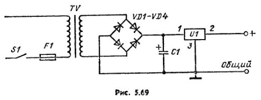
The circuit of the power source shown in Fig. 5.69 it uses the following components: electrolytic the condenser C1 - 10000 µf, 35 V, diodes VD1-VD4 - 50 V, 3 A; fuse F1 - 0.2 A; stabilizer U1 - 7605, 7805. The voltage on the secondary winding of the transformer at rated current 3 A has a value of 6.3 V. In the scheme used full-wave bridge rectifier. Capacitive filter ensures the receipt of unstabilized voltage of 8.5 V. Increasing the voltage on the secondary winding the transformer is undesirable because it will lead to a higher power, released in the stabilizer. The nominal value of the output current of the transformer is determined by the power output of the stabilizer.
When assembling the source components should be placed so that the mounting connections had the shortest length. You need to pay attention to the radiator of the voltage regulator have sufficient cooling surface. The source can be used to power a variety of electronic circuits, in particular of devices formed on an integrated logic circuits. TTL-type (transistor-transistor logic circuits).

The stabilized power supply with a negative output voltage of 5 V.
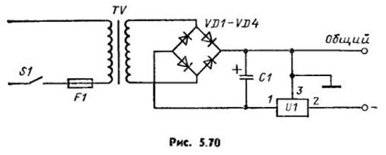
Diagram of a power source having a negative output voltage is given in Fig. 5.70. It differs from the previous in that it is used integral regulator 7905, which is "grounded" General output 3, as well as the positive output of full-wave bridge rectifier. Negative with respect to "ground" the output voltage of the rectifier input voltage the stabilizer. The parameters of components in the last two schemes completely identical.

Stable voltage source with an output voltage of 12 V.
If in the circuit shown in Fig. 5.69, instead of the integral stabilizer 7805 use the three-terminal regulator 7812, you will receive a power source with positive output voltage of 12 V. Of course, you want to make a number of changes related parameters some components. In particular, it is necessary to use a transformer with a higher voltage in the secondary winding increases as the level of the output voltage the power source.
Taking into account fluctuations of the mains voltage (115 V) and the desired value input voltage stabilizer, which should be at least 2.5 In more the output voltage, you can come to the conclusion that the RMS value of the voltage the secondary winding of the transformer must be at least 11 V. when the to reduce the capacitance of the filter capacitor to 7000 µf and rated current fuse must be increased to 0.5 A.
Using components with the same parameters in the circuit shown in Fig. 5.70, and using the integrated stabilizer, 7912, get the source with a negative output voltage, the absolute value of which is equal to 12 V. note, in that and in other case it is possible to use diodes with the same parameters: reverse voltage of 50 V and a direct current of 3 A.
These sources can be used to power a variety of electronic devices, designed to work with similar levels of supply voltage, in particular for any automotive devices.
Author: R. Treister


