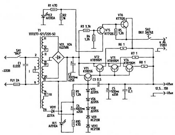
For lab ham when you want a stable source of supply (PS) with an output voltage of 12.5 V and current up to 5 A. suitable offer device. IE allows you to not only support high-load, but at the same time to recharge the battery (AB).

A voltage regulator transistors VT1 to VT4. The reference voltages are Zener VD9 and VD10. Their parameters determine the output the voltage source. Diodes VD5...VD8 are used for temperature compensation and adjustment the magnitude of the reference voltage. Resistor R9 sets the current through the Zener, resistors R6 R8...line currents of transistors.. VT2 VT4. The Capacitor C3 eliminates the excitation of the stabilizer. Capacitors C5 and C6 perform the functions output filter stabilizer Source is powered from the network 220 through a reduction In the transformer T1.
The mains voltage is applied to the primary winding the transformer via the fuse FU1, switch SA1 and the filter radio C1. From the secondary winding of the transformer voltage is applied to the diode bridge rectifier VD1...and diode VD4 VD11. Capacitors C2, C4 are to reduce the amplitude of the AC voltage at the input of the stabilizer. For the purpose more high rate stabilization plan applied filing the voltage at the input of the stabilizer with volitionally.
PI provides for optionally connecting emergency power pack (SB with 12 V). In the author's version is used for this battery battery type ST with a maximum current of 55 And For connecting a backup the battery serves as an electronic key transistors VT5 and VT6. The resistors R1 and R10 set the current through the LEDs HL1 and HL2. HL1 led indicates the presence of the mains voltage, and HL2 - activate emergency power. Food for recharging the battery is activated using SA2
Details. Switches SA1, SA2 (P2K-to-lock) can be replaced by any those designed for currents up to 6 A. for example. APF-125. APF-41.PG-22-FANUC The capacitor C1 is of type K73-9 on the operating voltage of 300 V. the Oxide capacitors C2, C4 and C5 - type K50-3S or similar to the operating voltage less than 25 V. the Remaining capacitors, except for S1 - type K10-17. MBM, C-3, CT-23 or similar Resistors R6. R8-B3R C5-5-5W, C5-16B-5BT. the rest - MLT-0,5. LEDs HL1, HL2 - ALA, ALA. ALA, ALA. L63SRC Transistor VT1 is replaced by CT, CT with any letter index, VT2...VT4 - CT. VT5 VT6... - CT. Diodes VD1...VD4 - type CD, D. D, D-16 indices B...G, CDW. CD; VD5...VD8 - D. CD, Kdim letter index. Zener VD9, VD10 provide a reference voltage that determines the output voltage of the stabilizer. They can be replaced by XB, DD. The transformer T1 can be replaced by a similar, given that the output the voltage across winding II under load should be 15...17 V. Winding III 's output voltage is 15 V. If the source is calculated based on the load current consumption of less than 2 A, T1 can be replaced by a transformer TC-26-1 the corresponding connection of the windings.
Transistors VT2...VT4 mounted on separate heat sinks with square cooling at least 120 cm2 each. In disabled mode load and AB quiescent current the output transistors is negligible. The operating temperature of the heat sinks transistors at maximum load (5 A) can reach 60. .70°C. ДиодыVD1...VD4HVD11 also mounted on separate heat sinks area of cooling at least 60 cm2. All the elements of the device are fixed inside any suitable housing, for example, from chargers automotive AB.
Author: A. Kashkarov, St.-Petersburg


