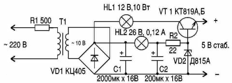
The CIS is "live" and THE button with the logic of caller ID on 155 series chips. This wild combination of low-imported schema with a powerful (watts!) logic requires an appropriate power supply, especially that of the "native" BP easily burns out!

In this scheme the output voltage and more current load, and in the operating mode (the sound of the loudspeaker) current consumption more, therefore requires stronger to suppress the surge voltage. Consider differences from the previous scheme. Rectifier bridge VD1 more powerful, capacitor filter feeding a larger capacity. The lamp is designed for HL2 more current (if the voltage of the secondary winding of the power transformer will allow you to install two lamps 12 In x 4 watts in parallel). Transistor VT1 more powerful to metal the plate of the body which can securely hold the two plates of the heat sink (or one plate, suitably bent).
Incandescent HL2 allows the Zener diode VD2 to work in a wider the range of supply voltage, and the capacitor C2 reduces the voltage ripple on the Zener diode. Resistor R2 is used to protect the transition b-e regulatory transistor from breakdown of the energy of the capacitor C2 is short-circuit output.
When building, you should monitor the output voltage with no load, when having to pick up a Zener diode! If the voltage under load will be to decrease or to listen on a background of 100 Hz, it is necessary to install a more powerful the lamp HL1, so that the voltage e of the transistor VT1 was within 2...4 V. If the voltage of the secondary winding of the transformer will be higher (20 In), the scheme will remain without changes, requiring only the selection of the lamp HL1. During installation it is necessary so to position the parts so that the lamps were at the top of the building, the warm air from they did not warm up other details, and radiation HL1 can be reflected to the outside using metal foil. Within 1 h of operation under load of heating parts should not be noticeable, for the same time short-circuit output should be warmed HL1, R1 to be warm. If this resistor is strongly heated, it is necessary to reduce the resistance and Vice versa (this depends on the data applied to the transformer).
Recall that if R1 will be very a little warm, while his burnout in the case of the stray circuit the transformer T1 is slightly higher! If the voltage very unstable, have to replace R1 filament 220 x 10...15 watts.


