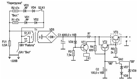
Many Amateurs make the supply units (PSUs) with electronic protection against overloads and short circuits. These schemes are a little complicated and not always work consistently. In my opinion, much easier and better systems at BP electromagnetic relays. The following is a description PSU with such a system of protection. BP has indication of switch and overload LEDs.
This PSU can be used to power any electronic devices with the supply voltage of 4.5 to 6 V, 9 V and the current consumption of 500 mA. Its very comfortable use for setting works because it contains a protection system against overload and short-circuit that ensures the safety of operations.

The operation of the circuit. When the power supply (see figure) in the network and the switch SA1 in the "On" position, the LEDs Shine VD1 (green) to "On" and VD3 (red color) "Overload". This suggests that BP prepared to work. Further click the button SB1 "Work". Relay K1, the led VD3 goes out. BP completely ready to work. On the output terminals appears selected using toggle switch SA2 voltage. When the device is connected to the output of the PSU, the whole supply current flows through the resistor R* (wire), creating it a certain voltage, which is applied to the transition b-e VT1 through direct the transition VD6. The voltage drop across the resistor R*U = IR, i.e. it depends on the current flowing in the constant resistance resistor R*. Thus, selecting the resistance of the resistor R*, we find the current protection, since the breakdown voltage of the Zener diode is constant.
The regulator circuit voltage characteristics has not. This is standard voltage compensation type. The transistor VT3 is placed on the radiator area 25-30 cm2. Thus, consumed in excess load current exceeds the pickup current protection voltage drop at R* exceeds the breakdown voltage of the direct transition VD6 (0.2 to 0.6 IN), and it is applied to transition B-e VT1. The avalanche transistor VT1 is closed, the relay K1 de-energized and disconnects the primary winding of T1 from the network, the voltage at the output of the PSU disappears. The led turns on VD3 (red) "Overload". BP after eliminate the overload or short circuit in the load must be run in work by pressing the button SB1 "Work".
Details. T1 - any transformer with a capacity of 15 watts with an output voltage of 12 V, providing a load current of 500 mA.
VD1 - ALL.G; VD2 and VD4 - DA; VD3 - ALA,B; VD6 - D; VD5 - CCA (CCA); VD7 - D; VD8 -2 x DA; VD9 - XA(168A); VT1 - MP; VT2 - P; VT3-CTA; K1 - relay RES-9 passport 200.
Author: O. G. Rashitov, Kiev


