


")

Often to power the antenna amplifier required the stabilized voltage source 9…12 V with a maximum current of load 20 mA. You can certainly use a power source of the amplifier the TV, however this is not always convenient. So it might take Autonomous power supply. And since it needs to provide reliable galvanic isolation from the mains, it is possible to use a simple transformerless the block with the quenching capacitor or resistor is unacceptable. To make same or to pick up the necessary step-down transformer is sometimes difficult. The solution to this situation would be to use pulsed low-power supply unit with a separating transformer on a ferrite ring cores.
Diagram of power supply of antenna amplifier shown in Fig. 1. It contains a generator of pulse signals on a powerful operating the amplifier DA1, which is fed from the rectifier VD1-VD4. Capacitor C1 dampens excessive voltage, and the capacitors C3 and C4 smooth the ripple of the rectified voltage.
The output current of the operational amplifier reaches CUD 300 mA, so the generator, collected on it by the scheme of the multivibrator, loaded directly to the primary winding of the transformer T1. Frequency generation - 25…30 kHz. The pulse voltage generated in the secondary winding of the transformer, rectified by diode VD6, VD7, and straightened the voltage is smoothed by the filter C5L1C6. The Zener diode VD8 stabilizes the output voltage of the power source.
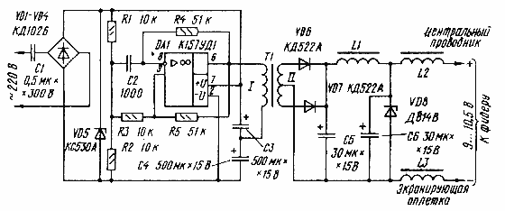
Fig. 1
The Zener diode VD5 directly to the device not involved - it only protects the operational amplifier and other elements from unacceptably high voltage in case of failure of generation or other malfunction.
To reduce cable television antenna unit is connected through decoupling chokes L2, L3.
Most of the mains voltage is about 90% - extinguishes the capacitor C1. It turns out that the generator is powered from the current source with an internal resistance Rc1?6,2 ohms, the value current through which may not exceed 30…33 mA. That's why the Zener diode VD8 in the secondary circuit of the transformer T1 is connected to the rectifier directly without damping resistor (active the resistance of the inductor L1 is not taken into account - it is not) that will not cause overload of the generator. The reason is that an increase in current in the secondary winding is increased and the current consumption of the oscillator. And since this current is limited by the capacitive impedance of the capacitor C1, the voltage of the generator is reduced accordingly, decreases the output voltage, and hence current consumption. So the Zener diode VD8 at the output of the rectifier will eat relatively stable current.
This and achieve a sufficiently high coefficient of stabilization:
KCT~(0,7…0,8)RC1/Rg,
where Rg, - dynamic resistance of the Zener diode VD8. When Rg=15 Ω FTC?300, which is enough to power amplifier such appointment. Without the amplifier, the current through the Zener diode VD8, does not exceed 25 mA, and the amplifier is reduced by the value current consumed by the amplifier.
All parts of the unit, in addition to the capacitor C1 and chokes L2, L3, placed and mounted on a printed circuit Board (Fig. 2). Chokes L2 and L3 include a hinged manner between the Board and connector amplifier, and the capacitor C1 are fixed on a separate Board.
Diodes VD1-VD4 can be KD105B - CDG,DB or rectifier unit KCA-CCG, CCA - CCG and VD6-VD7 - DA, D, D311, D, CDA, CDA - CDG. Zener diode VD5 can be composed of several series-connected Zener diodes with a total voltage stabilization 30…35 V. the Zener diode VD8 - for a voltage stabilization 9… 10,5 b and C maximum continuous the stabilizing current to 25 mA.
It is desirable that the capacitor C1 (capacity 0,47 0,56… CFF) was specially designed to work with alternating current, for example, MBGO, K42-19, C-4, K70-7, NGO rated voltage at least 300 V. It can be made up of two parallel connected capacitors MBM capacity of 0.25 µf rated voltage 500 or In series with a capacity of 1 UF voltage 160 V. the Capacitor C2 - KLS, km, KD, and C3-C6-C50-6, K50-24.
The transformer T1 and the inductor L1 is wound on a ring the magnetic circuits of size CHH mm ferrite 2000NM. Winding I transformer contains 35 turns, winding II - 40x2 turns of wire Sew-2 is 0.2 and the inductor L1 - 145…150 turns of the same wire. Chokes L2 and L3 DM type inductance 100…500 µh.
From the thoroughness of the implementation of the transformer depends electrical safety of the unit, therefore, despite its simplicity, it requires special attention. First of all, a file you need to round the sharp edges ring and wrap it in two layers of varnished cloth or adhesive tape. The wire is wound so as to winding located on opposite sides of the ring and the distance between them was not less than 5 mm from the Top of the winding is wrapped with insulation tape.
Chip CUD you can replace operating the amplifier medium speed, for example COD, with additional output stage transistors, as shown in the diagram Fig. 3.
In the pulse generator can also be used chip KUN, integrating it in the circuit shown in Fig. 4. But then it will be necessary to halve the number of turns of the primary winding transformer, twice to increase the capacitance of the capacitor C1 and to apply the Zener diode VD5 for voltage stabilization 15 17 Century…
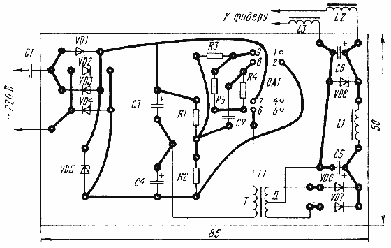
Fig. 2
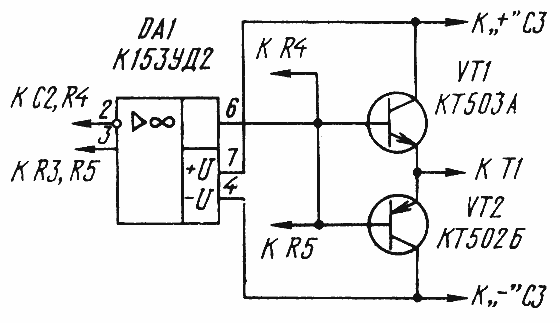
Fig. 3
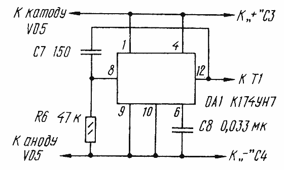
Fig. 4
Author: I. Nechaev, Kursk; Publication: www.cxem.net